Oki ML591 MICROLINE Reference Manual - Page 99
Graphics Commands for 24-Pin Printers
 |
View all Oki ML591 manuals
Add to My Manuals
Save this manual to your list of manuals |
Page 99 highlights
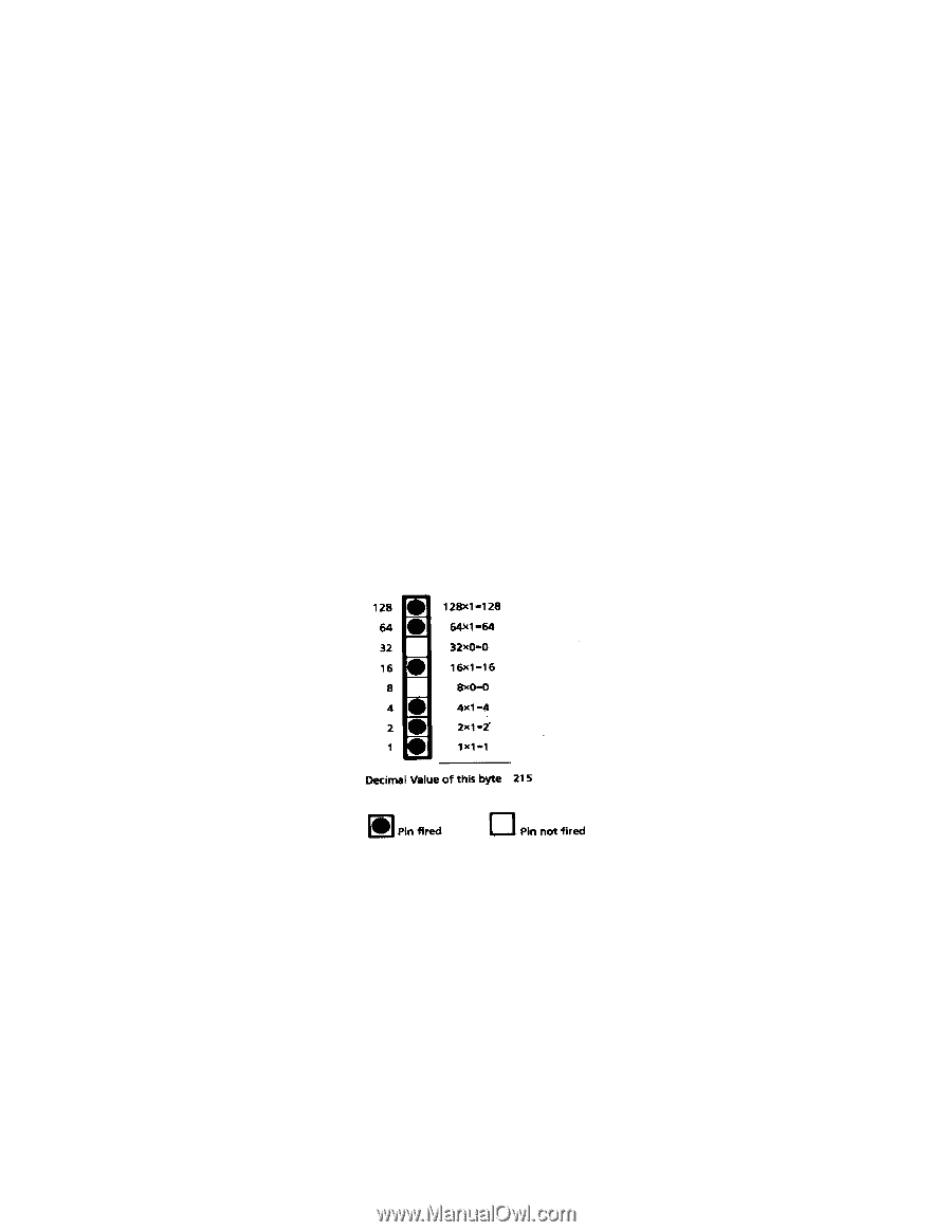
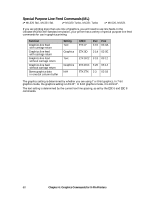
Chapter 7: Graphics Commands for 24-Pin Printers Overview Your printhead has one column of pins. Images are created as the pins "fire," striking the ribbon against the paper to produce dots. White spaces appear where the pins don't fire. In 8pin graphics, each column of dots is represented by a single byte of data. In the Epson LQ mode, Models ML390 Turbo, ML391 Turbo, ML590 and ML591 support 24-pin graphics, in which each dot column is represented by three bytes of data. When you program a graphic image, your program has to describe the pattern of dots you want to print. Graphics data, like all other data sent to the printer, consists of a series of bytes. Each of the eight bits in a byte of graphics data corresponds to one pin on the printhead. A bit's value can be either 1 or 0. When the printer receives the data, it interprets a bit with a value of 1 as a command to fire the corresponding pin. Bits that are set to 0 don't cause pins to fire. You can picture the byte as a column of 8 bits. In 8-pin graphics, the body of data is a series of these columns lined up next to each other. Instead of sending the data to the printer bit by bit, you'll probably want to convert this binary information into decimal or hexadecimal format for use with your programming language. In the figure below we show how to determine the decimal value for a given pattern of pins. For 24-pin graphics, you must perform this process a total of three times. Chapter 7: Graphics Commands for 24-Pin Printers 61
-
 1
1 -
2
-
3
-
4
-
5
-
6
-
7
-
8
-
9
-
10
-
11
-
12
-
13
-
14
-
15
-
16
-
17
-
18
-
19
-
20
-
21
-
22
-
23
-
24
-
25
-
26
-
27
-
28
-
29
-
30
-
31
-
32
-
33
-
34
-
35
-
36
-
37
-
38
-
39
-
40
-
41
-
42
-
43
-
44
-
45
-
46
-
47
-
48
-
49
-
50
-
51
-
52
-
53
-
54
-
55
-
56
-
57
-
58
-
59
-
60
-
61
-
62
-
63
-
64
-
65
-
66
-
67
-
68
-
69
-
70
-
71
-
72
-
73
-
74
-
75
-
76
-
77
-
78
-
79
-
80
-
81
-
82
-
83
-
84
-
85
-
86
-
87
-
88
-
89
-
90
-
91
-
92
-
93
-
 94
94 -
 95
95 -
 96
96 -
 97
97 -
 98
98 -
 99
99 -
 100
100 -
 101
101 -
 102
102 -
 103
103 -
 104
104 -
105
-
106
-
107
-
108
-
109
-
110
-
111
-
112
-
113
-
114
-
115
-
116
-
117
-
118
-
119
-
120
-
121
-
122
-
123
-
124
-
125
-
126
-
127
-
128
-
129
-
130
-
131
-
132
-
133
-
134
-
135
-
136
-
137
-
138
-
139
-
140
-
141
-
142
-
143
-
144
-
145
-
146
-
147
-
148
-
149
-
150
-
151
-
152
-
153
-
154
-
155
-
156
-
157
-
158
-
159
-
160
-
161
-
162
-
163
-
164
-
165
-
166
-
167
-
168
-
169
-
170
-
171
-
172
-
173
-
174
-
175
-
176
-
177
-
178
-
179
-
180
 |
 |