Oki ML591 MICROLINE Reference Manual - Page 165
Serial Interface, Table 103: Pin Assignments for Serial Interface Signals
 |
View all Oki ML591 manuals
Add to My Manuals
Save this manual to your list of manuals |
Page 165 highlights
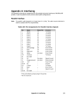
Serial Interface See your Printer Handbook for serial menu settings Note: The serial cable should be no longer than 50 ft. (15.25m). The cable must be shielded in order to comply with FCC requirements. Table 103: Pin Assignments for Serial Interface Signals Pin 1 2 3 4 5 6 7 8-10 11 12-19 20 21-25 Signal Protective Ground Transmitted Data Received Data Request to Send Not used Data Set Ready Signal Ground Not used Supervisory Send Data Not used Data Terminal Ready Not used Symbol PG TD RD TRS - DSR SG - SSD - DTR - Direction - From Printer To Printer From Printer - To Printer - - From Printer - From Printer - 134 Appendix A: Interfacing
-
 1
1 -
2
-
3
-
4
-
5
-
6
-
7
-
8
-
9
-
10
-
11
-
12
-
13
-
14
-
15
-
16
-
17
-
18
-
19
-
20
-
21
-
22
-
23
-
24
-
25
-
26
-
27
-
28
-
29
-
30
-
31
-
32
-
33
-
34
-
35
-
36
-
37
-
38
-
39
-
40
-
41
-
42
-
43
-
44
-
45
-
46
-
47
-
48
-
49
-
50
-
51
-
52
-
53
-
54
-
55
-
56
-
57
-
58
-
59
-
60
-
61
-
62
-
63
-
64
-
65
-
66
-
67
-
68
-
69
-
70
-
71
-
72
-
73
-
74
-
75
-
76
-
77
-
78
-
79
-
80
-
81
-
82
-
83
-
84
-
85
-
86
-
87
-
88
-
89
-
90
-
91
-
92
-
93
-
94
-
95
-
96
-
97
-
98
-
99
-
100
-
101
-
102
-
103
-
104
-
105
-
106
-
107
-
108
-
109
-
110
-
111
-
112
-
113
-
114
-
115
-
116
-
117
-
118
-
119
-
120
-
121
-
122
-
123
-
124
-
125
-
126
-
127
-
128
-
129
-
130
-
131
-
132
-
133
-
134
-
135
-
136
-
137
-
138
-
139
-
140
-
141
-
142
-
143
-
144
-
145
-
146
-
147
-
148
-
149
-
150
-
151
-
152
-
153
-
154
-
155
-
156
-
157
-
158
-
159
-
 160
160 -
 161
161 -
 162
162 -
 163
163 -
 164
164 -
 165
165 -
 166
166 -
 167
167 -
 168
168 -
 169
169 -
 170
170 -
171
-
172
-
173
-
174
-
175
-
176
-
177
-
178
-
179
-
180
 |
 |

Appendix A: Interfacing
134
Serial Interface
See your Printer Handbook for serial menu settings
Note:
The serial cable should be no longer than 50 ft. (15.25m). The cable must be
shielded
in
order to comply with FCC requirements.
Table 103: Pin Assignments for Serial Interface Signals
Pin
Signal
Symbol
Direction
1
Protective Ground
PG
–
2
Transmitted Data
TD
From Printer
3
Received Data
RD
To Printer
4
Request to Send
TRS
From Printer
5
Not used
–
–
6
Data Set Ready
DSR
To Printer
7
Signal Ground
SG
–
8–10
Not used
–
–
11
Supervisory Send Data
SSD
From Printer
12–19
Not used
–
–
20
Data Terminal Ready
DTR
From Printer
21–25
Not used
–
–