HP Integrity rx2800 rx2800 i2 User Service Guide - Page 112
PCI riser cage, Expansion slot covers, Expansion boards, Half-length expansion board
 |
View all HP Integrity rx2800 manuals
Add to My Manuals
Save this manual to your list of manuals |
Page 112 highlights
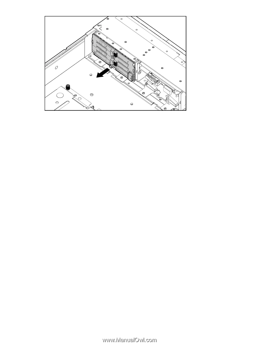
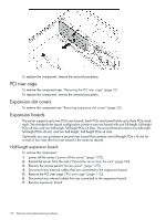
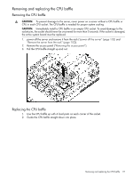
To replace the component, reverse the removal procedure. PCI riser cage To remove the component see. "Removing the PCI riser cage" (page 31). To replace the component, reverse the removal procedure. Expansion slot covers To remove the component see "Removing expansion slot covers" (page 32). Expansion boards The server supports up to two PCIe riser boards. Each PCIe riser board holds up to three PCIe cards each. The standard riser board configuration contains one riser board with one full-length, full-height PCIe x8 slot, and two half-length, full-height PCIe x4 slots. The second board contains one full-length, full-height PCIe x8 slot, and two half-length, half-height PCIe x4 slots. Optionally you can purchase a second riser board that contains one full-length PCIe x16 slot for a total of four slots (the first riser board is the same as above). Half-length expansion board To remove the component: 1. power off the server ("power off the server" (page 102)). 2. Extend the server from the rack ("Extend the server from the rack" (page 99)). 3. Remove the access panel ("Access panel" (page 107)). 4. Disconnect any external cables that are connected to the expansion board. 5. Remove the PCI riser cage ("PCI riser cage" (page 112)). 6. Disconnect any internal cables that are connected to the expansion board. 7. Remove expansion board. 112 Removal and replacement procedures
-
 1
1 -
2
-
3
-
4
-
5
-
6
-
7
-
8
-
9
-
10
-
11
-
12
-
13
-
14
-
15
-
16
-
17
-
18
-
19
-
20
-
21
-
22
-
23
-
24
-
25
-
26
-
27
-
28
-
29
-
30
-
31
-
32
-
33
-
34
-
35
-
36
-
37
-
38
-
39
-
40
-
41
-
42
-
43
-
44
-
45
-
46
-
47
-
48
-
49
-
50
-
51
-
52
-
53
-
54
-
55
-
56
-
57
-
58
-
59
-
60
-
61
-
62
-
63
-
64
-
65
-
66
-
67
-
68
-
69
-
70
-
71
-
72
-
73
-
74
-
75
-
76
-
77
-
78
-
79
-
80
-
81
-
82
-
83
-
84
-
85
-
86
-
87
-
88
-
89
-
90
-
91
-
92
-
93
-
94
-
95
-
96
-
97
-
98
-
99
-
100
-
101
-
102
-
103
-
104
-
105
-
106
-
 107
107 -
 108
108 -
 109
109 -
 110
110 -
 111
111 -
 112
112 -
 113
113 -
 114
114 -
 115
115 -
 116
116 -
 117
117 -
118
-
119
-
120
-
121
-
122
-
123
-
124
-
125
-
126
-
127
-
128
-
129
-
130
-
131
-
132
-
133
-
134
-
135
-
136
-
137
-
138
-
139
-
140
-
141
-
142
-
143
-
144
-
145
-
146
-
147
-
148
-
149
-
150
-
151
 |
 |