HP Integrity rx2800 rx2800 i2 User Service Guide - Page 21
Power supply, PCIe card slots
 |
View all HP Integrity rx2800 manuals
Add to My Manuals
Save this manual to your list of manuals |
Page 21 highlights
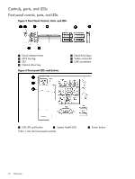
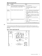
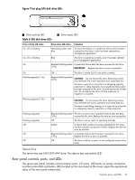
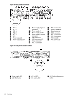
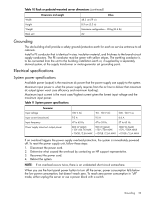
Table 7 Rear panel LEDs and buttons Name Power supply LED Status • Green = Normal • Off = System is off or power supply has failed UID LED/button • Blue = Identification • Flashing blue = Remote iLO session or a firmware flash update is in progress • Off = Off NIC/iLO 3 activity LED • Green = Network activity • Flashing green = Network activity • Off = No network activity NIC/iLO 3 link LED • Green = Network link • Off = No network link iLO 3 physical presence button The iLO 3 physical presence button enables you to reset iLO 3 and reset the user-specific values to factory default values. A momentary press causes a soft reset of iLO 3 when the button is released. The iLO 3 Physical Presence button enables you to reset iLO, enter TPM physical presence mode, and enter security override mode. • A momentary press of the button resets iLO and clears any security override or TPM physical presence mode that were initiated by this button. • A greater than 4 second less than 8 second press of the button places the system in physical presence mode for up to 15 minutes. • A greater than 8 second less than 12 second press of this button places iLO into security override mode for up to 15 minutes. Security override mode enables you to enter iLO without being challenged for a password enabling you to set up users. • The UID LED blinks once after holding the button for 4 seconds and once after holding the button for 8 seconds to help you gauge how long the button press has been held. Power supply The server is equipped with one or two power supplies, labeled PS1 and PS2. Each power supply has an ac input receptacle and an LED that indicates the power state of the server. The server has the following power states: standby power, full power, and off. To achieve the standby power state, plug the power cord into the appropriate receptacle at the rear of the server. To achieve full power, plug the power cord into the appropriate receptacle, and either push the power button or enter the iLO 3 MP PC command. In the off state, the power cords are not connected to a power source. Table 8 Power supply LED states LED state Off Green Indication No ac power Full power on; normal operation PCIe card slots The server has two PCIe riser boards that support up to three PCIe cards each. Wake-on-LAN is not enabled on any of the PCIe slots. PCIe hot plug is not supported on the server. Controls, ports, and LEDs 21
-
 1
1 -
2
-
3
-
4
-
5
-
6
-
7
-
8
-
9
-
10
-
11
-
12
-
13
-
14
-
15
-
 16
16 -
 17
17 -
 18
18 -
 19
19 -
 20
20 -
 21
21 -
 22
22 -
 23
23 -
 24
24 -
 25
25 -
 26
26 -
27
-
28
-
29
-
30
-
31
-
32
-
33
-
34
-
35
-
36
-
37
-
38
-
39
-
40
-
41
-
42
-
43
-
44
-
45
-
46
-
47
-
48
-
49
-
50
-
51
-
52
-
53
-
54
-
55
-
56
-
57
-
58
-
59
-
60
-
61
-
62
-
63
-
64
-
65
-
66
-
67
-
68
-
69
-
70
-
71
-
72
-
73
-
74
-
75
-
76
-
77
-
78
-
79
-
80
-
81
-
82
-
83
-
84
-
85
-
86
-
87
-
88
-
89
-
90
-
91
-
92
-
93
-
94
-
95
-
96
-
97
-
98
-
99
-
100
-
101
-
102
-
103
-
104
-
105
-
106
-
107
-
108
-
109
-
110
-
111
-
112
-
113
-
114
-
115
-
116
-
117
-
118
-
119
-
120
-
121
-
122
-
123
-
124
-
125
-
126
-
127
-
128
-
129
-
130
-
131
-
132
-
133
-
134
-
135
-
136
-
137
-
138
-
139
-
140
-
141
-
142
-
143
-
144
-
145
-
146
-
147
-
148
-
149
-
150
-
151
 |
 |
