HP Integrity rx2800 rx2800 i2 User Service Guide - Page 69
Troubleshooting, Methodology, General troubleshooting methodology
 |
View all HP Integrity rx2800 manuals
Add to My Manuals
Save this manual to your list of manuals |
Page 69 highlights
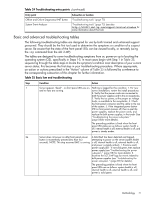
5 Troubleshooting The purpose of this chapter is to provide a preferred methodology (strategies and procedures) and tools for troubleshooting the server error and fault conditions. Methodology General troubleshooting methodology There are multiple entry points to the troubleshooting process, dependent upon your level of troubleshooting expertise, the tools/processes/procedures which you have at your disposal, and the nature of the system fault or failure. Typically, you select from a set of symptoms, ranging from very simple (system LED is blinking) to the most difficult (Machine Check Abort (MCA)) has occurred. The following is a list of symptom examples: NOTE: Your output might differ from the output in the examples in this book depending on your server and its configuration. • Front panel LED blinking • System alert present on console • System won't power-up • System won't boot • Error/Event Message received • Machine Check Abort (MCA) occurred Narrow down the observed problem to the specific troubleshooting procedure required. Isolate the failure to a specific part of the server, so you can perform more detailed troubleshooting. For example: • Problem- Front panel LED blinking NOTE: The front panel health LEDs flash amber with a warning indication, or flash red with a fault indication. ◦ System Alert on console? Analyze the alert by using the system event log (SEL), to identify the last error logged by the server. Use the iLO 3 MP commands to view the SEL, either through the iLO 3 MP serial text interface, or through telnet, Secure Shell, or through the web GUI on the iLO 3 MP LAN. You should now have a good idea about which area of the system requires further analysis. For example, if the symptom was "system won't power-up", the initial troubleshooting procedure may indicate a problem with the dc power rail not coming up after the power switch was turned on. You have now reached the point where the failed CRU has been identified and needs to be replaced. Perform the specific removal and replacement procedure, and verification steps. NOTE: If multiple CRUs are identified as part of the solution, a fix cannot be guaranteed unless all identified failed CRUs are replaced. There may be specific recovery procedures you need to perform to finish the repair. For example, if the system board is replaced, you need to restore customer specific information. Methodology 69
-
 1
1 -
2
-
3
-
4
-
5
-
6
-
7
-
8
-
9
-
10
-
11
-
12
-
13
-
14
-
15
-
16
-
17
-
18
-
19
-
20
-
21
-
22
-
23
-
24
-
25
-
26
-
27
-
28
-
29
-
30
-
31
-
32
-
33
-
34
-
35
-
36
-
37
-
38
-
39
-
40
-
41
-
42
-
43
-
44
-
45
-
46
-
47
-
48
-
49
-
50
-
51
-
52
-
53
-
54
-
55
-
56
-
57
-
58
-
59
-
60
-
61
-
62
-
63
-
 64
64 -
 65
65 -
 66
66 -
 67
67 -
 68
68 -
 69
69 -
 70
70 -
 71
71 -
 72
72 -
 73
73 -
 74
74 -
75
-
76
-
77
-
78
-
79
-
80
-
81
-
82
-
83
-
84
-
85
-
86
-
87
-
88
-
89
-
90
-
91
-
92
-
93
-
94
-
95
-
96
-
97
-
98
-
99
-
100
-
101
-
102
-
103
-
104
-
105
-
106
-
107
-
108
-
109
-
110
-
111
-
112
-
113
-
114
-
115
-
116
-
117
-
118
-
119
-
120
-
121
-
122
-
123
-
124
-
125
-
126
-
127
-
128
-
129
-
130
-
131
-
132
-
133
-
134
-
135
-
136
-
137
-
138
-
139
-
140
-
141
-
142
-
143
-
144
-
145
-
146
-
147
-
148
-
149
-
150
-
151
 |
 |