HP Integrity rx2800 rx2800 i2 User Service Guide - Page 118
Removing and replacing a CPU and heat sink module
 |
View all HP Integrity rx2800 manuals
Add to My Manuals
Save this manual to your list of manuals |
Page 118 highlights
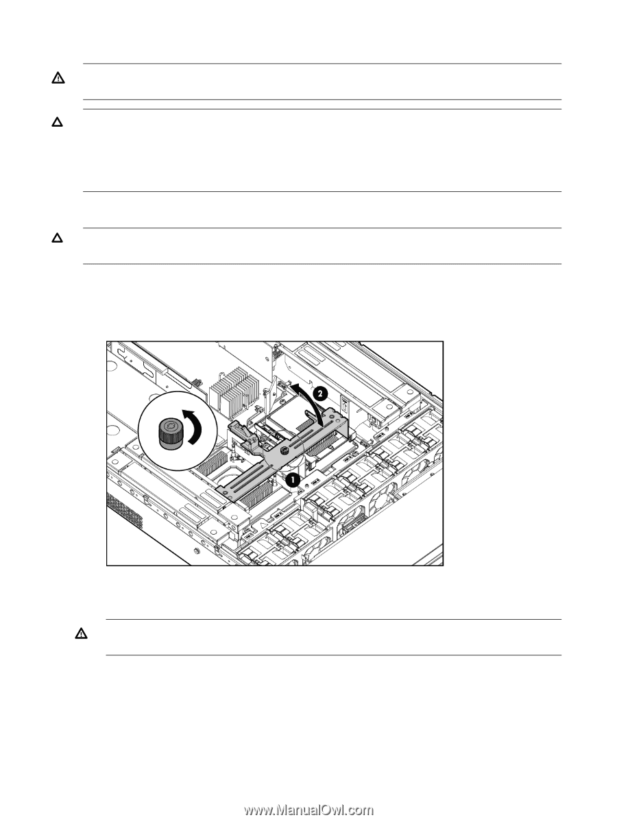
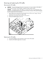
Removing and replacing a CPU and heat sink module WARNING! To reduce the risk of personal injury from hot surfaces, allow the drives and the internal system components to cool before touching them. CAUTION: To prevent possible server malfunction, do not mix CPUs of different speeds or cache sizes. CAUTION: Removing a CPU will cause the DIMM loading rules to change. See "Memory configurations" (page 34) and use the loading rules for two CPUs. If you do not perform these procedures, then any memory associated with the removed CPU will not be seen by the system. Removing a CPU and heat sink module CAUTION: To prevent thermal instability and damage to the server, do not separate the CPU module from the heat sink. 1. power off the server and remove it from the rack ("power off the server" (page 102) and "Remove the server from the rack" (page 102)). 2. Remove the access panel ("Removing the access panel" (page 30)). 3. Open the CPU cage. 4. Disconnect the power cord (see 1 below) 5. Rotate the CPU locking handle up and back until it reaches a hard stop (see 2 below) WARNING! The heat sink locking lever can constitute a pinch hazard, keep your hands on top of the lever during installation to avoid personal injury. 6. Pull both plastic tabs out (see 3 below). 118 Removal and replacement procedures
-
 1
1 -
2
-
3
-
4
-
5
-
6
-
7
-
8
-
9
-
10
-
11
-
12
-
13
-
14
-
15
-
16
-
17
-
18
-
19
-
20
-
21
-
22
-
23
-
24
-
25
-
26
-
27
-
28
-
29
-
30
-
31
-
32
-
33
-
34
-
35
-
36
-
37
-
38
-
39
-
40
-
41
-
42
-
43
-
44
-
45
-
46
-
47
-
48
-
49
-
50
-
51
-
52
-
53
-
54
-
55
-
56
-
57
-
58
-
59
-
60
-
61
-
62
-
63
-
64
-
65
-
66
-
67
-
68
-
69
-
70
-
71
-
72
-
73
-
74
-
75
-
76
-
77
-
78
-
79
-
80
-
81
-
82
-
83
-
84
-
85
-
86
-
87
-
88
-
89
-
90
-
91
-
92
-
93
-
94
-
95
-
96
-
97
-
98
-
99
-
100
-
101
-
102
-
103
-
104
-
105
-
106
-
107
-
108
-
109
-
110
-
111
-
112
-
 113
113 -
 114
114 -
 115
115 -
 116
116 -
 117
117 -
 118
118 -
 119
119 -
 120
120 -
 121
121 -
 122
122 -
 123
123 -
124
-
125
-
126
-
127
-
128
-
129
-
130
-
131
-
132
-
133
-
134
-
135
-
136
-
137
-
138
-
139
-
140
-
141
-
142
-
143
-
144
-
145
-
146
-
147
-
148
-
149
-
150
-
151
 |
 |