HP Integrity rx2800 rx2800 i2 User Service Guide - Page 83
System build-Up troubleshooting procedure, I/O Risers
 |
View all HP Integrity rx2800 manuals
Add to My Manuals
Save this manual to your list of manuals |
Page 83 highlights
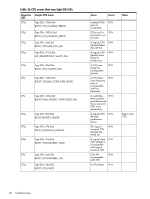
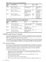
• * I/O Risers • * Memory risers • I/O Riser • * PCIe Expansion boards • * SAS battery • * DIMMs • * Cooling Fans (6) NOTE: Items preceded by an asterisk in the lists above have associated diagnostic LEDs, which indicate device fault or failure. System build-Up troubleshooting procedure Use this procedure only when the system powers on and remain powered on but does not enter into or pass power-on self test (POST) or does not boot to the UEFI menu. 1. Remove the ac power cord from each power supply and extend the server, if racked. 2. Remove all of the SAS disk drives from the front of the server. 3. Remove the top cover to gain access to, and remove, everything but the I/O backplane and system board CRUs. NOTE: In the following steps, CRU and FRU are used interchangeably. 4. Plug in the ac power cords and the iLO 3 MP and system console should display and you should have the following CRU IDs listed after executing the MP DF command. Your display may not exactly match the display shown: FRU IDs: -------02-Power Converter 03-Power Supply 0 04-Power Supply 1 05-Diagnostic Panel 06-Front Panel 00-Motherboard If you do not see all of the above CRU IDs then concentrate on the missing CRU IDs. You should eventually end up with the following Alert (IPMI) event for this action as read from the SEL. NOTE: Your display may not exactly match the display shown. Log Entry 4: Dec 2005 00:00:09 Alert Level 5: Critical Keyword: Type-02 257100 2453760 Missing FRU device - Memory Logged by: Baseboard Management Controller, Sensor: Entity Presence 0x2000000009020050 FF01807115250300 If you do not get the above Alert Level 5 (IPMI) event, but get another sort of high level alert, try replacing the I/O backplane. Then, examine the pins on the midplane board, and if necessary, replace the midplane board. 5. The next step would be to add one pair of DIMMs. Remember to remove the ac power cords before making this configuration change. Here is the output of the MP DF command you should expect at this point (this example has two ranks of DIMMs installed). Supported configurations 83
-
 1
1 -
2
-
3
-
4
-
5
-
6
-
7
-
8
-
9
-
10
-
11
-
12
-
13
-
14
-
15
-
16
-
17
-
18
-
19
-
20
-
21
-
22
-
23
-
24
-
25
-
26
-
27
-
28
-
29
-
30
-
31
-
32
-
33
-
34
-
35
-
36
-
37
-
38
-
39
-
40
-
41
-
42
-
43
-
44
-
45
-
46
-
47
-
48
-
49
-
50
-
51
-
52
-
53
-
54
-
55
-
56
-
57
-
58
-
59
-
60
-
61
-
62
-
63
-
64
-
65
-
66
-
67
-
68
-
69
-
70
-
71
-
72
-
73
-
74
-
75
-
76
-
77
-
 78
78 -
 79
79 -
 80
80 -
 81
81 -
 82
82 -
 83
83 -
 84
84 -
 85
85 -
 86
86 -
 87
87 -
 88
88 -
89
-
90
-
91
-
92
-
93
-
94
-
95
-
96
-
97
-
98
-
99
-
100
-
101
-
102
-
103
-
104
-
105
-
106
-
107
-
108
-
109
-
110
-
111
-
112
-
113
-
114
-
115
-
116
-
117
-
118
-
119
-
120
-
121
-
122
-
123
-
124
-
125
-
126
-
127
-
128
-
129
-
130
-
131
-
132
-
133
-
134
-
135
-
136
-
137
-
138
-
139
-
140
-
141
-
142
-
143
-
144
-
145
-
146
-
147
-
148
-
149
-
150
-
151
 |
 |