HP Integrity rx2800 rx2800 i2 User Service Guide - Page 82
System event log review, Supported configurations, Server block diagram
 |
View all HP Integrity rx2800 manuals
Add to My Manuals
Save this manual to your list of manuals |
Page 82 highlights
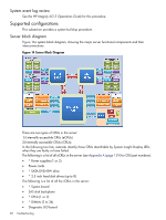
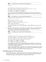
System event log review See the HP Integrity iLO 3 Operations Guide for this procedure. Supported configurations This subsection provides a system build-up procedure. Server block diagram Figure 14a system block diagram, showing the major server functional components and their interconnections: Figure 14 Server Block Diagram There are two types of CRUs in the server: 1) Externally accessible CRUs (eCRUs) 2) Internally accessible CRUs (iCRUs). In the following two lists, asterisks identify those CRUs identifiable by System Insight Display LEDs when they are faulty or have failed. The following is a list of all eCRUs in the server (see Appendix A (page 129) for CRU part numbers): • * Power supplies (1 or 2) • Power cords • * SATA DVD+RW drive • * 2.5 inch hard disk drives (up to 8) The following is a list of all the iCRUs in the server: • * System board • SAS disk backplane • * CPUs (1 or 2) • * DIMMs (2 to 24) • Diagnostic LED board 82 Troubleshooting
-
 1
1 -
2
-
3
-
4
-
5
-
6
-
7
-
8
-
9
-
10
-
11
-
12
-
13
-
14
-
15
-
16
-
17
-
18
-
19
-
20
-
21
-
22
-
23
-
24
-
25
-
26
-
27
-
28
-
29
-
30
-
31
-
32
-
33
-
34
-
35
-
36
-
37
-
38
-
39
-
40
-
41
-
42
-
43
-
44
-
45
-
46
-
47
-
48
-
49
-
50
-
51
-
52
-
53
-
54
-
55
-
56
-
57
-
58
-
59
-
60
-
61
-
62
-
63
-
64
-
65
-
66
-
67
-
68
-
69
-
70
-
71
-
72
-
73
-
74
-
75
-
76
-
 77
77 -
 78
78 -
 79
79 -
 80
80 -
 81
81 -
 82
82 -
 83
83 -
 84
84 -
 85
85 -
 86
86 -
 87
87 -
88
-
89
-
90
-
91
-
92
-
93
-
94
-
95
-
96
-
97
-
98
-
99
-
100
-
101
-
102
-
103
-
104
-
105
-
106
-
107
-
108
-
109
-
110
-
111
-
112
-
113
-
114
-
115
-
116
-
117
-
118
-
119
-
120
-
121
-
122
-
123
-
124
-
125
-
126
-
127
-
128
-
129
-
130
-
131
-
132
-
133
-
134
-
135
-
136
-
137
-
138
-
139
-
140
-
141
-
142
-
143
-
144
-
145
-
146
-
147
-
148
-
149
-
150
-
151
 |
 |
