HP Integrity rx2800 rx2800 i2 User Service Guide - Page 89
Power LED button, Troubleshooting the cooling subsystem, Cooling subsystem behavior
 |
View all HP Integrity rx2800 manuals
Add to My Manuals
Save this manual to your list of manuals |
Page 89 highlights
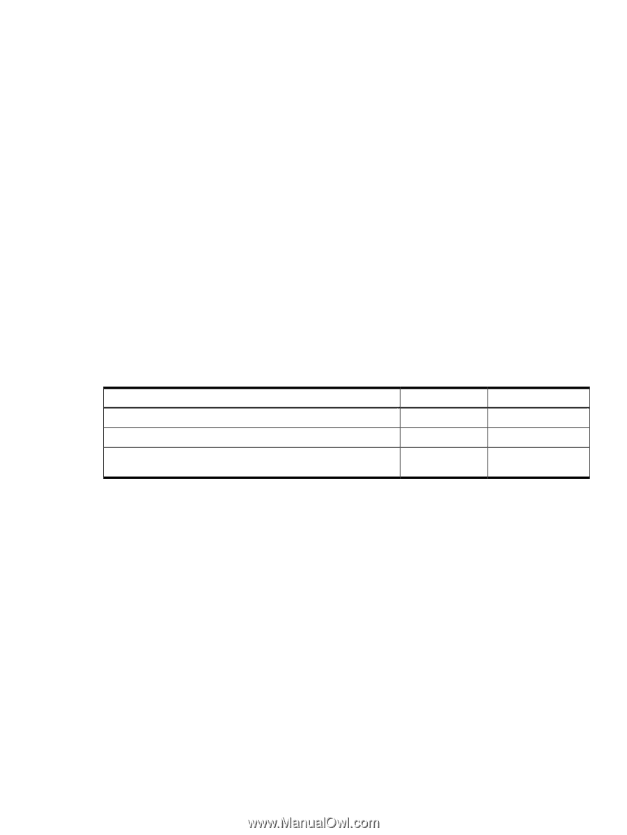
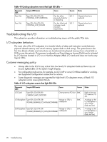
• +12 V dc comes up and all of the cooling fans and the various Voltage Regulators come up sequentially. • iLO3 signals when the server is ready to come out of reset (clocks are programmed and stable, etc.). • The server is brought out of reset, and begins the boot process. Power LED button The front panel system power LED indicates the status of system power. It is incorporated inside the power button itself. The power button has a momentary switch (as opposed to a latching switch) that is recessed or covered to prevent accidental activation or deactivation. If the OS is up, pressing the power button for less than four seconds results in a graceful shutdown of the operating system and a subsequent removal of system power. Pressing the power button for greater than four seconds results in a hard shutdown (system power removed). While the server is booting (before the system has passed UEFI_EXIT_BOOT_SERVICES), the BMC immediately powers the server off on a button press, since there is no concept of soft shutdown in this state. In the event that the OS is absent or hung, or that the manageability subsystem (specifically the BMC) in the server is not responding, a greater than four second press of the power button is required to power off the system (a less than four second press on the power button has no effect). To ensure that the system powers up in a deterministic fashion, the power button must be masked for four seconds after a power-down. Table 39 Power LED States Definition No ac power to the system System power is turned on System is shut down, but ac and housekeeping (standby) power are active. Flash rate LED Off Steady Steady LED color Green Amber For high availability and safety reasons, this LED runs off the power rails, rather than under firmware control. Troubleshooting the cooling subsystem The fans located within the server provide N+1 redundancy for the server using six identical dual fan assembly CRUs. In turn, each dual fan assembly CRU provides additional N+1 redundancy for the fan cooling zone it controls. Each dual fan assembly CRU is identified by the server as fans 1 through 6 both for logging purposes and for fault identification on the diagnostic LED panel. Cooling fan CRU failures are identified visually by a single green LED on the dual fan assembly CRU that is turned on when one or both of the fans fail; logged as an IPMI event by fan sensor logic; and identified as a fan assembly CRU failure by iLO 3 turning on the appropriate LEDs on the System Insight Display panel. Cooling subsystem behavior iLO 3 controls fan speed on ambient air temperatures, chip temperatures, server configuration, and fan operation or failure. Air is drawn through the front of the server and pushed out the rear by the cooling fans. You can display fan status remotely with the iLO 3 MP ps command. Within the server, temperature sensors report server temperatures to iLO 3, which controls fan speed based on this information. Troubleshooting the cooling subsystem 89
-
 1
1 -
2
-
3
-
4
-
5
-
6
-
7
-
8
-
9
-
10
-
11
-
12
-
13
-
14
-
15
-
16
-
17
-
18
-
19
-
20
-
21
-
22
-
23
-
24
-
25
-
26
-
27
-
28
-
29
-
30
-
31
-
32
-
33
-
34
-
35
-
36
-
37
-
38
-
39
-
40
-
41
-
42
-
43
-
44
-
45
-
46
-
47
-
48
-
49
-
50
-
51
-
52
-
53
-
54
-
55
-
56
-
57
-
58
-
59
-
60
-
61
-
62
-
63
-
64
-
65
-
66
-
67
-
68
-
69
-
70
-
71
-
72
-
73
-
74
-
75
-
76
-
77
-
78
-
79
-
80
-
81
-
82
-
83
-
 84
84 -
 85
85 -
 86
86 -
 87
87 -
 88
88 -
 89
89 -
 90
90 -
 91
91 -
 92
92 -
 93
93 -
 94
94 -
95
-
96
-
97
-
98
-
99
-
100
-
101
-
102
-
103
-
104
-
105
-
106
-
107
-
108
-
109
-
110
-
111
-
112
-
113
-
114
-
115
-
116
-
117
-
118
-
119
-
120
-
121
-
122
-
123
-
124
-
125
-
126
-
127
-
128
-
129
-
130
-
131
-
132
-
133
-
134
-
135
-
136
-
137
-
138
-
139
-
140
-
141
-
142
-
143
-
144
-
145
-
146
-
147
-
148
-
149
-
150
-
151
 |
 |