HP Integrity rx2800 rx2800 i2 User Service Guide - Page 123
IMPORTANT, CAUTION, Remove the rear retaining screw.
 |
View all HP Integrity rx2800 manuals
Add to My Manuals
Save this manual to your list of manuals |
Page 123 highlights
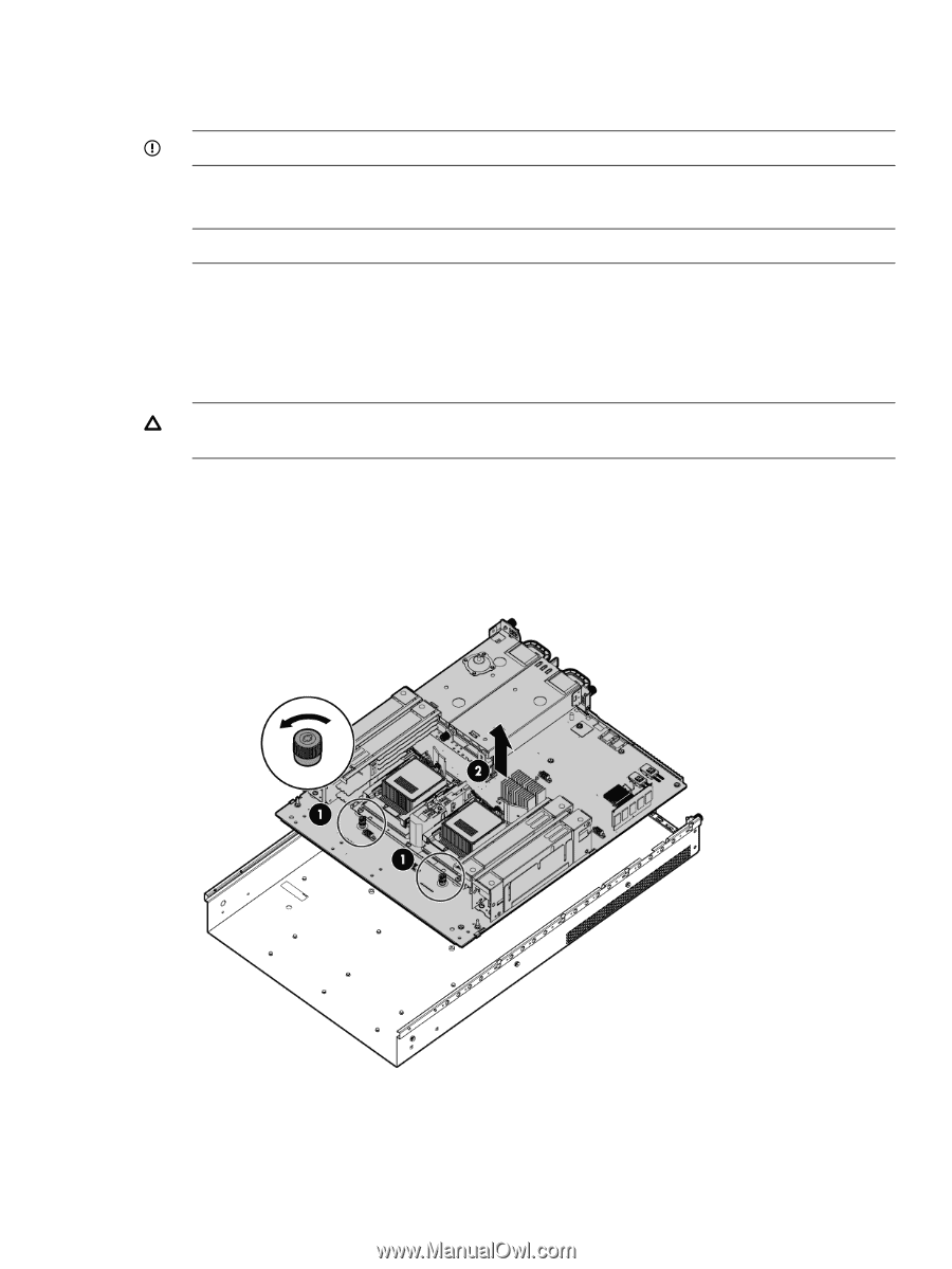
6. Remove the PCI riser cage ("PCI riser cage" (page 112)). 7. Remove all DIMMs risers ("DIMMs" (page 120)). 8. Remove all CPU heat sink modules ("Removing a CPU and heat sink module" (page 118)). IMPORTANT: Place CPU pin covers over the sockets to protect the pins. 9. Remove the intrusion switch cable ("Intrusion switch cable" (page 122)). 10. Disconnect all cables connected to the system board. NOTE: The video and serial connectors are attached with hex screws. 11. Remove the hot-swap fans from the fan cage ("Hot-swap fan" (page 109)). 12. Remove the fan cage. 13. Remove the SAS cache module. 14. Remove the super capacitor pack ("Removing the super capacitor pack" (page 114)). 15. Remove the power supply backplane ("Power supply backplane" (page 110)). CAUTION: To prevent damage to the server or expansion boards, power off the server and remove all ac power cords before removing or installing the PCI riser cage. 16. Remove hex screws from the rear video connector and serial connector 17. Remove the rear retaining screw. 18. Loosen the two system board thumbscrews. 19. Remove the system board from the chassis by pushing it toward the front and then lifting it up. 20. Remove four screws on the power supply cage, and remove power supply cage. 21. Loosen the screws of the CPU cage, and remove the CPU cage. 22. Remove the two memory riser assemblies. 23. Remove the seven screws on the main board to separate it from the sub pan. System board 123
-
 1
1 -
2
-
3
-
4
-
5
-
6
-
7
-
8
-
9
-
10
-
11
-
12
-
13
-
14
-
15
-
16
-
17
-
18
-
19
-
20
-
21
-
22
-
23
-
24
-
25
-
26
-
27
-
28
-
29
-
30
-
31
-
32
-
33
-
34
-
35
-
36
-
37
-
38
-
39
-
40
-
41
-
42
-
43
-
44
-
45
-
46
-
47
-
48
-
49
-
50
-
51
-
52
-
53
-
54
-
55
-
56
-
57
-
58
-
59
-
60
-
61
-
62
-
63
-
64
-
65
-
66
-
67
-
68
-
69
-
70
-
71
-
72
-
73
-
74
-
75
-
76
-
77
-
78
-
79
-
80
-
81
-
82
-
83
-
84
-
85
-
86
-
87
-
88
-
89
-
90
-
91
-
92
-
93
-
94
-
95
-
96
-
97
-
98
-
99
-
100
-
101
-
102
-
103
-
104
-
105
-
106
-
107
-
108
-
109
-
110
-
111
-
112
-
113
-
114
-
115
-
116
-
117
-
 118
118 -
 119
119 -
 120
120 -
 121
121 -
 122
122 -
 123
123 -
 124
124 -
 125
125 -
 126
126 -
 127
127 -
 128
128 -
129
-
130
-
131
-
132
-
133
-
134
-
135
-
136
-
137
-
138
-
139
-
140
-
141
-
142
-
143
-
144
-
145
-
146
-
147
-
148
-
149
-
150
-
151
 |
 |