HP Integrity rx2800 rx2800 i2 User Service Guide - Page 46
Applying standby power to the server, Connecting to the LAN, Connecting and setting up the console
 |
View all HP Integrity rx2800 manuals
Add to My Manuals
Save this manual to your list of manuals |
Page 46 highlights
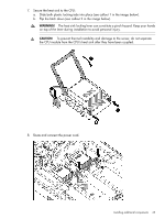
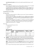
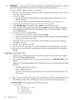
Applying standby power to the server 1. Plug the power cord into the receptacle in power supply 1. Plug the other end of the power cord into an ac outlet. NOTE: The LED on the power supply does not illuminate in the standby power state. The LED is green when the server is powered on to full power. If the power restore feature is set to Always On through the iLO 3 MP PR command, the server automatically powers on to the full power state when the power cord is plugged into the server. 2. If the server has two power supplies, plug the second power cord into the power supply 2. Plug the other end of the power cord into an ac outlet. Connecting to the LAN The server has four LAN ports that provide network connectivity. Figure 10 (page 20) shows the available LAN ports for the server. 1. Obtain valid IP addresses for each LAN port you plan to activate. 2. Connect the LAN cable from an available LAN port into a live connection on the network. Connecting and setting up the console Setting up the console To set up the console (either physically or remotely), determine the following before starting the set up: • Determine the physical access method to connect cables. There are two physical connections to the iLO 3 MP: ◦ RS-232 ◦ LAN • Configure the Integrity iLO 3 MP and assign an IP address if necessary. Though there are several methods to configure the LAN, DHCP with DNS is the preferred method. DHCP with DNS comes preconfigured with default factory settings, including a default user account and password. Other options include: ◦ Local RS-232 serial port ◦ Remote or modem port Connecting to a host console Use one of the following ports: • RS-232 serial port. Use this port to access the iLO 3 MP through the serial. • iLO 3 MP LAN port. Use this port to access the iLO 3 MP through the LAN. • VGA port. Use this port to access a graphics console. (The iLO 3 MP cannot be accessed using this port .) Physical access Figure 10 (page 20) shows the server ports and required connection components. After you are physically connected, configure the console. 46 Installing the server
-
 1
1 -
2
-
3
-
4
-
5
-
6
-
7
-
8
-
9
-
10
-
11
-
12
-
13
-
14
-
15
-
16
-
17
-
18
-
19
-
20
-
21
-
22
-
23
-
24
-
25
-
26
-
27
-
28
-
29
-
30
-
31
-
32
-
33
-
34
-
35
-
36
-
37
-
38
-
39
-
40
-
 41
41 -
 42
42 -
 43
43 -
 44
44 -
 45
45 -
 46
46 -
 47
47 -
 48
48 -
 49
49 -
 50
50 -
 51
51 -
52
-
53
-
54
-
55
-
56
-
57
-
58
-
59
-
60
-
61
-
62
-
63
-
64
-
65
-
66
-
67
-
68
-
69
-
70
-
71
-
72
-
73
-
74
-
75
-
76
-
77
-
78
-
79
-
80
-
81
-
82
-
83
-
84
-
85
-
86
-
87
-
88
-
89
-
90
-
91
-
92
-
93
-
94
-
95
-
96
-
97
-
98
-
99
-
100
-
101
-
102
-
103
-
104
-
105
-
106
-
107
-
108
-
109
-
110
-
111
-
112
-
113
-
114
-
115
-
116
-
117
-
118
-
119
-
120
-
121
-
122
-
123
-
124
-
125
-
126
-
127
-
128
-
129
-
130
-
131
-
132
-
133
-
134
-
135
-
136
-
137
-
138
-
139
-
140
-
141
-
142
-
143
-
144
-
145
-
146
-
147
-
148
-
149
-
150
-
151
 |
 |
