HP Integrity rx2800 rx2800 i2 User Service Guide - Page 34
DIMMs, Memory configurations, Memory riser board locations and slot IDs
 |
View all HP Integrity rx2800 manuals
Add to My Manuals
Save this manual to your list of manuals |
Page 34 highlights
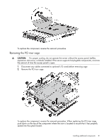
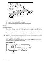
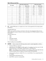
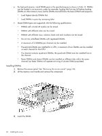
5. Connect any internal cables required by the expansion board. 6. Install the PCI riser cage back into the chassis. 7. Connect any external cables required by the expansion board. DIMMs Memory configurations The server has 24 system memory DIMM slots located on 4 memory riser boards (6 DIMMs per riser). You can access the memory riser boards without removing the airflow guide or the I/O card cage. The DIMMs are partitioned by the number of CPUs installed in the server. If you have only one CPU installed in the system, you can only use 12 of the 24 memory slots. CAUTION: Observe all ESD safety precautions before attempting this procedure. Failure to follow ESD safety precautions can result in damage to the server. Memory riser board locations and slot IDs Install DIMMs into the appropriate risers attached to the system board. Each slot has a unique ID. See Figure 2 (page 11) for memory riser locations. Figure 13 DIMM slot IDs 34 Installing the server
-
 1
1 -
2
-
3
-
4
-
5
-
6
-
7
-
8
-
9
-
10
-
11
-
12
-
13
-
14
-
15
-
16
-
17
-
18
-
19
-
20
-
21
-
22
-
23
-
24
-
25
-
26
-
27
-
28
-
 29
29 -
 30
30 -
 31
31 -
 32
32 -
 33
33 -
 34
34 -
 35
35 -
 36
36 -
 37
37 -
 38
38 -
 39
39 -
40
-
41
-
42
-
43
-
44
-
45
-
46
-
47
-
48
-
49
-
50
-
51
-
52
-
53
-
54
-
55
-
56
-
57
-
58
-
59
-
60
-
61
-
62
-
63
-
64
-
65
-
66
-
67
-
68
-
69
-
70
-
71
-
72
-
73
-
74
-
75
-
76
-
77
-
78
-
79
-
80
-
81
-
82
-
83
-
84
-
85
-
86
-
87
-
88
-
89
-
90
-
91
-
92
-
93
-
94
-
95
-
96
-
97
-
98
-
99
-
100
-
101
-
102
-
103
-
104
-
105
-
106
-
107
-
108
-
109
-
110
-
111
-
112
-
113
-
114
-
115
-
116
-
117
-
118
-
119
-
120
-
121
-
122
-
123
-
124
-
125
-
126
-
127
-
128
-
129
-
130
-
131
-
132
-
133
-
134
-
135
-
136
-
137
-
138
-
139
-
140
-
141
-
142
-
143
-
144
-
145
-
146
-
147
-
148
-
149
-
150
-
151
 |
 |
