HP Integrity rx2800 rx2800 i2 User Service Guide - Page 114
Battery-backed write cache procedures, Removing the cache module, Removing the super capacitor pack
 |
View all HP Integrity rx2800 manuals
Add to My Manuals
Save this manual to your list of manuals |
Page 114 highlights
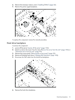
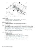
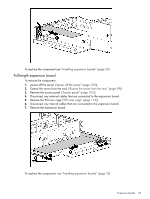
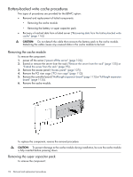
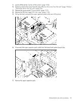
Battery-backed write cache procedures Two types of procedures are provided for the BBWC option: • Removal and replacement of failed components: ◦ Removing the cache module ◦ Removing the battery or super capacitor pack • Recovery of cached data from a failed server ("Recovering data from the battery-backed write cache" (page 116)) CAUTION: Do not detach the cable that connects the battery pack to the cache module. Detaching the cable causes any unsaved data in the cache module to be lost. Removing the cache module To remove the component: 1. power off the server ("power off the server" (page 102)). 2. Extend or remove the server from the rack ("Remove the server from the rack" (page 102)) or "Extend the server from the rack" (page 99)). 3. Remove the access panel ("Access panel" (page 107)). 4. Remove the PCI riser cage ("PCI riser cage" (page 112)). 5. Remove the controller board ("Half-length expansion board" (page 112)) or"Full-length expansion board" (page 113))). 6. Remove the cache module. To replace the component, reverse the removal procedure. CAUTION: To prevent damage to the cache module during installation, be sure the cache module is fully inserted before pressing down. Removing the super capacitor pack To remove the component: 114 Removal and replacement procedures
-
 1
1 -
2
-
3
-
4
-
5
-
6
-
7
-
8
-
9
-
10
-
11
-
12
-
13
-
14
-
15
-
16
-
17
-
18
-
19
-
20
-
21
-
22
-
23
-
24
-
25
-
26
-
27
-
28
-
29
-
30
-
31
-
32
-
33
-
34
-
35
-
36
-
37
-
38
-
39
-
40
-
41
-
42
-
43
-
44
-
45
-
46
-
47
-
48
-
49
-
50
-
51
-
52
-
53
-
54
-
55
-
56
-
57
-
58
-
59
-
60
-
61
-
62
-
63
-
64
-
65
-
66
-
67
-
68
-
69
-
70
-
71
-
72
-
73
-
74
-
75
-
76
-
77
-
78
-
79
-
80
-
81
-
82
-
83
-
84
-
85
-
86
-
87
-
88
-
89
-
90
-
91
-
92
-
93
-
94
-
95
-
96
-
97
-
98
-
99
-
100
-
101
-
102
-
103
-
104
-
105
-
106
-
107
-
108
-
 109
109 -
 110
110 -
 111
111 -
 112
112 -
 113
113 -
 114
114 -
 115
115 -
 116
116 -
 117
117 -
 118
118 -
 119
119 -
120
-
121
-
122
-
123
-
124
-
125
-
126
-
127
-
128
-
129
-
130
-
131
-
132
-
133
-
134
-
135
-
136
-
137
-
138
-
139
-
140
-
141
-
142
-
143
-
144
-
145
-
146
-
147
-
148
-
149
-
150
-
151
 |
 |
