HP Integrity rx2800 rx2800 i2 User Service Guide - Page 122
Intrusion switch cable, System board, Disconnect the Systems Insight Display cable.
 |
View all HP Integrity rx2800 manuals
Add to My Manuals
Save this manual to your list of manuals |
Page 122 highlights
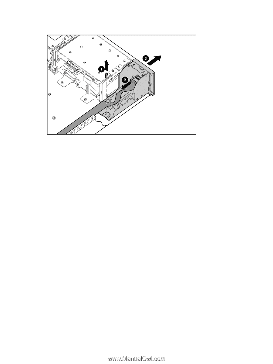
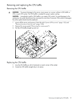
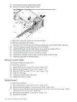
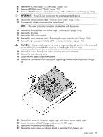
7. Disconnect the Systems Insight Display cable. 8. Remove the Systems Insight Display module. To replace the component, reverse the removal procedure. If installing a replacement SID module: 1. Retain the retain the SID bezel, the transparent light pipe, and the black rubber light pipe. 2. Install the transparent plastic light pipe onto the SID bezel. 3. Install the SID bezel onto the metal chassis, ensuring the four latches all lock. 4. Put the black rubber light pipe onto the plastic light pipe. 5. Install the SID board by securing it with the two screws. 6. Fasten the two hexagon screws on the front of SID bezel to the VGA port. 7. Install the component as described above. Intrusion switch cable The intrusion switch screws face CPU 0. To remove the component: 1. power off the server ("power off the server" (page 102)). 2. Remove the access panel ("Access panel" (page 107)). 3. Remove the PCI riser cage ("PCI riser cage" (page 112)). 4. Open the CPU cage. 5. Using a screwdriver Remove the switch. 6. Unplug the mating connector System board To remove the component: 1. Power off the server ("power off the server" (page 102)). 2. Remove all power supplies ("Hot-swap power supply" (page 106)). 3. Extend or remove the server from the rack ("Remove the server from the rack" (page 102)) or "Extend the server from the rack" (page 99)). 4. Remove the access panel ("Access panel" (page 107)). 5. Remove the air baffle. 122 Removal and replacement procedures
-
 1
1 -
2
-
3
-
4
-
5
-
6
-
7
-
8
-
9
-
10
-
11
-
12
-
13
-
14
-
15
-
16
-
17
-
18
-
19
-
20
-
21
-
22
-
23
-
24
-
25
-
26
-
27
-
28
-
29
-
30
-
31
-
32
-
33
-
34
-
35
-
36
-
37
-
38
-
39
-
40
-
41
-
42
-
43
-
44
-
45
-
46
-
47
-
48
-
49
-
50
-
51
-
52
-
53
-
54
-
55
-
56
-
57
-
58
-
59
-
60
-
61
-
62
-
63
-
64
-
65
-
66
-
67
-
68
-
69
-
70
-
71
-
72
-
73
-
74
-
75
-
76
-
77
-
78
-
79
-
80
-
81
-
82
-
83
-
84
-
85
-
86
-
87
-
88
-
89
-
90
-
91
-
92
-
93
-
94
-
95
-
96
-
97
-
98
-
99
-
100
-
101
-
102
-
103
-
104
-
105
-
106
-
107
-
108
-
109
-
110
-
111
-
112
-
113
-
114
-
115
-
116
-
 117
117 -
 118
118 -
 119
119 -
 120
120 -
 121
121 -
 122
122 -
 123
123 -
 124
124 -
 125
125 -
 126
126 -
 127
127 -
128
-
129
-
130
-
131
-
132
-
133
-
134
-
135
-
136
-
137
-
138
-
139
-
140
-
141
-
142
-
143
-
144
-
145
-
146
-
147
-
148
-
149
-
150
-
151
 |
 |