Lantronix X300 Series X300 Series User Guide Rev B - Page 70
LED Configuration, System > LED Configuration
 |
View all Lantronix X300 Series manuals
Add to My Manuals
Save this manual to your list of manuals |
Page 70 highlights
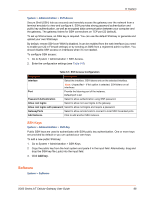
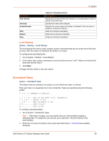
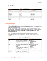
3. Click Save. Shortcut @reboot @yearly @annually @monthly @weekly @daily @midnight @hourly 8: System Table 8-9 Cron Shortcuts Equivalent (none) 0 0 1 1 * 0 0 1 1 * 0 0 1 * * 0 0 * * 0 0 0 * * * 0 0 * * * 0 * * * * Description At system startup Every year Every year Every month Every week Every day Every day Every hour LED Configuration System > LED Configuration The X300 series gateway provides 7 LEDs to indicate status and activity. For a description of the default LED behaviors, see LEDs. The LED can be controlled by various system events, which is selected by the trigger option. Depending on the trigger, additional options must be specified. See Table 8-10 which lists some trigger descriptions. The UI displays some triggers not listed in the table, but these are not recommended to be used. Note: LED configuration should be done by experienced personnel. Use care when modifying the LEDs as improper configuration may cause LED indicators to be misread or missed. Trigger none timer defaulton Table 8-10 Trigger Descriptions Description The LED is always in the default state. This is useful to declare an LED to be always ON. Examples LED always on: LED name: any LED Default: On Trigger: none The LED blinks with the configured On/ Off frequency. Options: On-state delay: time in milliseconds that the LED is On. Off-state delay: time in milliseconds that the LED is Off. LED is 100ms On / 200ms Off: LED name: any LED Default: On Trigger: timer On-State Delay: 100 Off-State Delay: 200 This trigger option is deprecated. Use trigger = none and default = On instead. X300 Series IoT Cellular Gateway User Guide 70
-
 1
1 -
2
-
3
-
4
-
5
-
6
-
7
-
8
-
9
-
10
-
11
-
12
-
13
-
14
-
15
-
16
-
17
-
18
-
19
-
20
-
21
-
22
-
23
-
24
-
25
-
26
-
27
-
28
-
29
-
30
-
31
-
32
-
33
-
34
-
35
-
36
-
37
-
38
-
39
-
40
-
41
-
42
-
43
-
44
-
45
-
46
-
47
-
48
-
49
-
50
-
51
-
52
-
53
-
54
-
55
-
56
-
57
-
58
-
59
-
60
-
61
-
62
-
63
-
64
-
 65
65 -
 66
66 -
 67
67 -
 68
68 -
 69
69 -
 70
70 -
 71
71 -
 72
72 -
 73
73 -
 74
74 -
 75
75 -
76
-
77
-
78
-
79
-
80
-
81
-
82
-
83
-
84
-
85
-
86
-
87
-
88
-
89
-
90
-
91
-
92
-
93
-
94
-
95
-
96
-
97
-
98
-
99
-
100
-
101
-
102
-
103
-
104
-
105
-
106
-
107
-
108
-
109
-
110
-
111
-
112
-
113
-
114
-
115
-
116
-
117
-
118
-
119
-
120
-
121
-
122
-
123
-
124
-
125
-
126
-
127
-
128
-
129
-
130
-
131
-
132
-
133
-
134
-
135
-
136
-
137
-
138
-
139
-
140
-
141
-
142
-
143
-
144
-
145
-
146
-
147
-
148
-
149
-
150
-
151
-
152
-
153
-
154
-
155
-
156
-
157
-
158
-
159
-
160
-
161
-
162
-
163
-
164
-
165
-
166
-
167
-
168
-
169
-
170
-
171
-
172
-
173
-
174
-
175
-
176
-
177
-
178
-
179
-
180
-
181
-
182
-
183
-
184
-
185
-
186
-
187
-
188
-
189
-
190
-
191
-
192
-
193
-
194
-
195
-
196
-
197
-
198
-
199
-
200
-
201
-
202
-
203
-
204
-
205
-
206
-
207
-
208
-
209
-
210
-
211
-
212
-
213
-
214
-
215
-
216
 |
 |
