Netgear PS110 PS110 Reference Manual - Page 148
Logical Printer Configuration, lists the fields of the Logical Printer configuration
 |
UPC - 606449002218
View all Netgear PS110 manuals
Add to My Manuals
Save this manual to your list of manuals |
Page 148 highlights
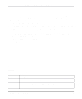
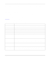
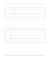
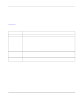
Installation and Reference for the Model PS104/PS105/PS110 Print Server Logical Printer Configuration For the print server with one printer port, there are three logical printers. For print server models with two printer ports, there are eight logical printers. You can define how each one of the logical printers will map into the physical port. The following table shows how the four parameters are related to each logical printer. The same entries are repeated for each logical printer. Table 7-13 lists the fields of the Logical Printer configuration, describes the functions, and explains how to provide information in each field. Table 7-13. Parameters and Definitions for Logical Printer Configuration Field Description L1 Physical Port L1 String Before Job L1 String After Job L1 Convert LF to LF+CR Selects into which physical printer port the logical port L1 is mapped. Provides the control character string to send to the printer before the first character of the job is sent. One example of such an application would be switching to landscape mode when printing to the logical port. The character string must be in hexadecimal format as the example illustrates: • ASCII = [Esc]&l0O Hexadecimal = 1B266C304F • ASCII = [Esc]&l1O Hexadecimal = 1B266C314F Provides the control character string to send to the printer after the last character of the job is sent to the printer. The character string must be in hexadecimal format as illustrated in the previous example included in this table. Add a carriage return (CR) every time the line feed (LF) character code is received by the print server when any print data is sent to this logical port. 7-20 Using Advanced Management Tools
-
 1
1 -
2
-
3
-
4
-
5
-
6
-
7
-
8
-
9
-
10
-
11
-
12
-
13
-
14
-
15
-
16
-
17
-
18
-
19
-
20
-
21
-
22
-
23
-
24
-
25
-
26
-
27
-
28
-
29
-
30
-
31
-
32
-
33
-
34
-
35
-
36
-
37
-
38
-
39
-
40
-
41
-
42
-
43
-
44
-
45
-
46
-
47
-
48
-
49
-
50
-
51
-
52
-
53
-
54
-
55
-
56
-
57
-
58
-
59
-
60
-
61
-
62
-
63
-
64
-
65
-
66
-
67
-
68
-
69
-
70
-
71
-
72
-
73
-
74
-
75
-
76
-
77
-
78
-
79
-
80
-
81
-
82
-
83
-
84
-
85
-
86
-
87
-
88
-
89
-
90
-
91
-
92
-
93
-
94
-
95
-
96
-
97
-
98
-
99
-
100
-
101
-
102
-
103
-
104
-
105
-
106
-
107
-
108
-
109
-
110
-
111
-
112
-
113
-
114
-
115
-
116
-
117
-
118
-
119
-
120
-
121
-
122
-
123
-
124
-
125
-
126
-
127
-
128
-
129
-
130
-
131
-
132
-
133
-
134
-
135
-
136
-
137
-
138
-
139
-
140
-
141
-
142
-
 143
143 -
 144
144 -
 145
145 -
 146
146 -
 147
147 -
 148
148 -
 149
149 -
 150
150 -
 151
151 -
 152
152 -
 153
153 -
154
-
155
-
156
-
157
-
158
-
159
-
160
-
161
-
162
-
163
-
164
-
165
-
166
-
167
-
168
-
169
-
170
-
171
-
172
-
173
-
174
-
175
-
176
-
177
-
178
 |
 |