Netgear PS110 PS110 Reference Manual - Page 28
Connecting Devices to the Print Server
 |
UPC - 606449002218
View all Netgear PS110 manuals
Add to My Manuals
Save this manual to your list of manuals |
Page 28 highlights
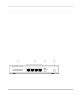
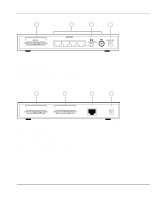
Installation and Reference for the Model PS104/PS105/PS110 Print Server Connecting Devices to the Print Server The Model PS104 Print Server has four 10BASE-T network ports. The Model PS105 Print Server has four 10BASE-T network ports and one BNC network port. The Model PS110 Print Server has one 10/100BASE-T network port that is autosensing and will support either 10 Mbps or 100 Mbps connections, depending on the connected device. The 10/100BASE-T network port operates in half-duplex mode. Ports 2 through 4 on the Model PS104 Print Server are permanently configured for MDI-X wiring; port 1 can be set to MDI (Uplink) or MDI-X (Normal) by using the Normal/Uplink push button switch. The BNC port 1 on the Model PS105 Print Server is for network connections with BNC cabling. The BNC-T connection included in the package contents must be used with the coaxial cable for a 10BASE 2 connection to other network devices that have a BNC port. To terminate the connection on the last device in the network segment, you must use the BNC terminator, which is included in the package contents. The one network port on the Model PS110 Print Server is permanently configured for Uplink wiring. Refer to Table 2-1 for setting the Normal/Uplink push button switch and for selecting either a crossover or straight-through cable when connecting your print server to other devices. Table 2-1. Cable Selection and Normal/Uplink Push Button Settings Connecting Network Port Model PS104 Print Server Port 1 set to Uplink Port 1 set to Normal Ports 2 through 4 Model PS105 Print Server Port 1 Port 2 set to Uplink Ports 3 through 5 Model PS110 Print Server Connecting Device Hub or switch PC or router PC PC Hub or switch PC Hub or switch PC Cable Used Straight-through cable Straight-through cable Straight-through cable BNC cable with 50 ohm terminator Straight-through cable Straight-through cable Straight-through cable Crossover cable Note: Ethernet specifications limit the twisted pair cable (called a twisted pair segment) extended from a network port to 100 meters in length. 2-2 Installation
-
 1
1 -
2
-
3
-
4
-
5
-
6
-
7
-
8
-
9
-
10
-
11
-
12
-
13
-
14
-
15
-
16
-
17
-
18
-
19
-
20
-
21
-
22
-
 23
23 -
 24
24 -
 25
25 -
 26
26 -
 27
27 -
 28
28 -
 29
29 -
 30
30 -
 31
31 -
 32
32 -
 33
33 -
34
-
35
-
36
-
37
-
38
-
39
-
40
-
41
-
42
-
43
-
44
-
45
-
46
-
47
-
48
-
49
-
50
-
51
-
52
-
53
-
54
-
55
-
56
-
57
-
58
-
59
-
60
-
61
-
62
-
63
-
64
-
65
-
66
-
67
-
68
-
69
-
70
-
71
-
72
-
73
-
74
-
75
-
76
-
77
-
78
-
79
-
80
-
81
-
82
-
83
-
84
-
85
-
86
-
87
-
88
-
89
-
90
-
91
-
92
-
93
-
94
-
95
-
96
-
97
-
98
-
99
-
100
-
101
-
102
-
103
-
104
-
105
-
106
-
107
-
108
-
109
-
110
-
111
-
112
-
113
-
114
-
115
-
116
-
117
-
118
-
119
-
120
-
121
-
122
-
123
-
124
-
125
-
126
-
127
-
128
-
129
-
130
-
131
-
132
-
133
-
134
-
135
-
136
-
137
-
138
-
139
-
140
-
141
-
142
-
143
-
144
-
145
-
146
-
147
-
148
-
149
-
150
-
151
-
152
-
153
-
154
-
155
-
156
-
157
-
158
-
159
-
160
-
161
-
162
-
163
-
164
-
165
-
166
-
167
-
168
-
169
-
170
-
171
-
172
-
173
-
174
-
175
-
176
-
177
-
178
 |
 |