TASCAM SS-R200 100 SS-R200 SS-CDR200 Owners Manual - Page 15
Rear panel, CONTROL I/O RS-232C connector
 |
View all TASCAM SS-R200 manuals
Add to My Manuals
Save this manual to your list of manuals |
Page 15 highlights
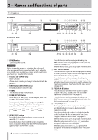
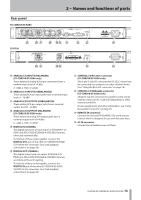
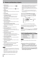
Rear panel SS-CDR200/SS-R200 SS-R100 2 − Names and functions of parts g ANALOG L/R INPUTS (BALANCED) (SS-CDR200/SS-R200 only) These balanced analog XLR input connectors have a nominal input level of +4 dBu. (1: GND, 2: HOT, 3: COLD) h ANALOG L/R INPUTS (UNBALANCED) These analog RCA pin input jacks have a nominal input level of −10 dBV. j ANALOG L/R OUTPUTS (UNBALANCED) These analog RCA pin output jacks have a nominal output level of −10 dBV. k ANALOG L/R OUTPUTS (BALANCED) (SS-CDR200/SS-R200 only) These balanced analog XLR output jacks have a nominal output level of +4 dBu. (1: GND, 2: HOT, 3: COLD) l DIGITAL IN (COAXIAL) This digital input jack accepts inputs in IEC60958-3 (S/ PDIF) and AES3-2003/IEC60958-4 (AES/EBU) formats (detected automatically). To link two of these units together, connect the DIGITAL OUT jack of the other SS-CDR200/SS-R200/ SS-R100 to this connector. (See "Link playback connections" on page 38.) ; DIGITAL OUT (COAXIAL) This digital output jack can output IEC60958-3 (S/ PDIF) and AES3-2003/IEC60958-4 (AES/EBU) formats according to the unit's setting. To link two of these units together, connect the DIGITAL IN jack of the other SS-CDR200/SS-R200/ SS-R100 to this connector. (See "Link playback connections" on page 38.) z CONTROL I/O RS-232C connector (SS-CDR200/SS-R200 only) This 9-pin D-sub I/O connector for RS-232C control can be connected to a computer or other external device. (See "Using the RS-232C connector" on page 76.) x CONTROL I/O PARALLEL connector (SS-CDR200/SS-R200 only) 25-pin D-sub I/O connector for parallel control can be used to connect an RC-SS20 (sold separately) or other external controller. For pin assignments and other information, see "Using the parallel connector" on page 76. c REMOTE IN connector Connect the included TASCAM RC-SS2 wired remote control, which is designed for use with this unit, here. v AC IN connector Connect the included power cord here. TASCAM SS-CDR200/SS-R200/SS-R100 15
-
 1
1 -
2
-
3
-
4
-
5
-
6
-
7
-
8
-
9
-
 10
10 -
 11
11 -
 12
12 -
 13
13 -
 14
14 -
 15
15 -
 16
16 -
 17
17 -
 18
18 -
 19
19 -
 20
20 -
21
-
22
-
23
-
24
-
25
-
26
-
27
-
28
-
29
-
30
-
31
-
32
-
33
-
34
-
35
-
36
-
37
-
38
-
39
-
40
-
41
-
42
-
43
-
44
-
45
-
46
-
47
-
48
-
49
-
50
-
51
-
52
-
53
-
54
-
55
-
56
-
57
-
58
-
59
-
60
-
61
-
62
-
63
-
64
-
65
-
66
-
67
-
68
-
69
-
70
-
71
-
72
-
73
-
74
-
75
-
76
-
77
-
78
-
79
-
80
-
81
-
82
-
83
-
84
 |
 |
