TASCAM SS-R200 100 SS-R200 SS-CDR200 Owners Manual - Page 76
− Using control I/O (SS-CDR200/SS-R200 only), Using the RS-232C connector, Using the parallel
 |
View all TASCAM SS-R200 manuals
Add to My Manuals
Save this manual to your list of manuals |
Page 76 highlights
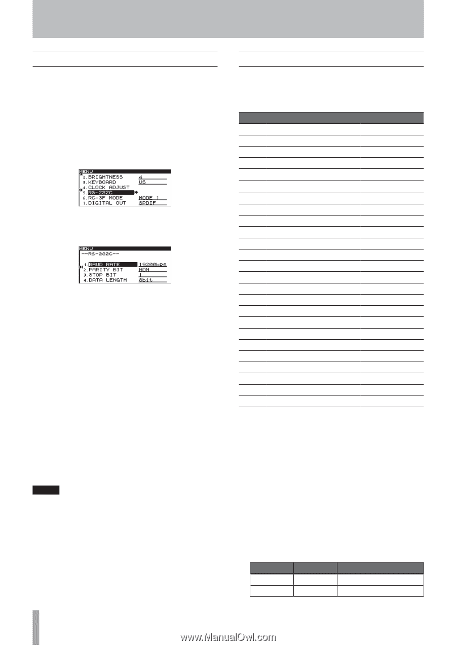
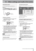
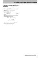
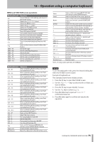
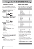
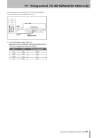
14 − Using control I/O (SS-CDR200/SS-R200 only) Using the RS-232C connector Using the 9-pin, D-sub CONTROL I/O RS-232C connector, which is compliant with RS-232C standards, you can control the unit via this serial connection from a computer or other external device. Use the menu to make settings related to communication. 1 Press the MENU [JOG] button (or remote control MENU button) to open the MENU screen. 2 Open the UTILITY menu. 3 Select RS-232C. 4 Press the MULTI JOG dial or , [LOCK] button (or remote control ENTER or t button) to open the RS-232C setting screen. 5 Set the items on the RS-232C screen. BAUD RATE Set the baud rate (communication speed). Options: 4800 bps, 9600 bps, 19200 bps (default value), 38400 bps PARITY BIT Set the parity bit use. Options: NON (none, default value), EVEN, ODD STOP BIT Set the stop bit. Options: 1 (default value), 2 DATA LENGTH Set the data length. Options: 7, 8 (default value) 6 After setting each item, press the HOME/DISPLAY button (or remote control HOME/DISP button) to return to the Home Screen. NOTE • RS-232C settings are retained even after the power is turned OFF. • For details on the unit's RS-232C command protocol, please contact TASCAM customer support. 76 TASCAM SS-CDR200/SS-R200/SS-R100 Using the parallel connector Using the CONTROL I/O PARALLEL connector, you can control this unit through serial connection with a TASCAM RC-SS20 or other external controller. The pin assignments are as follows. Pin Function 1 GND 2 PLAY/Flash 1 3 STOP/Flash 2 4 RECORD/Flash 3 5 / (Next)/Flash 4 6 . (Previous)/Flash 5 7 Flash Load 8 Fader Start 9 Flash Tally 10 Ready Tally 11 Record Tally 12 Stop Tally 13 Play Tally 14 Remote Select*2 15 Ready/Flash 6 16 Call/Flash 7 17 Auto Cue/Flash 8 18 Auto Ready/Flash 9 19 Pitch/Flash 10 20 Flash Page*3 21 EOM Tally 22 Device Select Tally 1*4 23 - 24 Device Select Tally 2*4 25 +5V*1 IN/OUT - In In In In In In In Out Out Out Out Out In In In In In In In Out Out - Out - In: Active low external command reception (Functions when connected to GND for at least 30 msec usually and at least 1 sec when recording an MP3 file) Out: Signal for transport status display by open drain (maximum voltage 50 V, maximum current 50 mA) *1 Maximum supplied current 100 mA. *2 Pin 14 (Remote Select) When set to high, input pins with two functions shown above with a "/" (pins 2-6 and 15-19) use the first function, and can be used for ordinary parallel control. When set to low, these input pins function as flash start keys. *3 Pin 20 (Flash Page) When pin 14 (Remote Select) is set to low, the high/low setting of pin 20 determines the track assignments. #14 #20 Low High Low Low Flash start tracks 1-10 11-20
-
 1
1 -
2
-
3
-
4
-
5
-
6
-
7
-
8
-
9
-
10
-
11
-
12
-
13
-
14
-
15
-
16
-
17
-
18
-
19
-
20
-
21
-
22
-
23
-
24
-
25
-
26
-
27
-
28
-
29
-
30
-
31
-
32
-
33
-
34
-
35
-
36
-
37
-
38
-
39
-
40
-
41
-
42
-
43
-
44
-
45
-
46
-
47
-
48
-
49
-
50
-
51
-
52
-
53
-
54
-
55
-
56
-
57
-
58
-
59
-
60
-
61
-
62
-
63
-
64
-
65
-
66
-
67
-
68
-
69
-
70
-
 71
71 -
 72
72 -
 73
73 -
 74
74 -
 75
75 -
 76
76 -
 77
77 -
 78
78 -
 79
79 -
 80
80 -
 81
81 -
82
-
83
-
84
 |
 |