HP 450c Service Manual - Page 125
Introduction, Reassembly, Safety Precautions - review
 |
View all HP 450c manuals
Add to My Manuals
Save this manual to your list of manuals |
Page 125 highlights
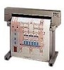
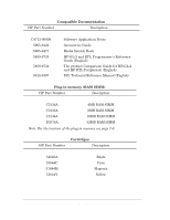
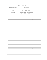
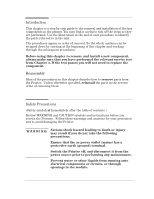
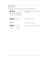
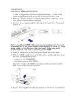
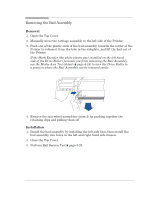
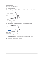
Introduction This chapter is a step by step guide to the removal and installation of the key components in the printer. You may find it useful to tick off the steps as they are performed. Use the illustration at the end of each procedure to identify the parts referred to in the text. The procedures appear in order of removal. So the whole machine can be stripped down by starting at the beginning of this chapter and working through the subsequent procedures. Before using this chapter to remove and install a new component, always make sure that you have performed the relevant service test from Chapter 4. If the test passes you will not need to replace the component. Reassembly Most of the procedures in this chapter describe how to remove parts from the Printer. Unless otherwise specified, reinstall the parts in the reverse order of removing them. Safety Precautions (Safety symbols ' Immediately after the table of contents.) Review WARNING and CAUTION symbols and instructions before you service the Printers. Follow these warnings and cautions for your protection and to avoid damaging the Printer. WĂAĂRĂNĂIĂNĂG Serious shock hazard leading to death or injury may result if you do not take the following precautions: Ensure that the ac power outlet (mains) has a protective earth (ground) terminal. Switch the Printer off, and disconnect it from the power source prior to performing any maintenance. Prevent water or other liquids from running onto electrical components or circuits, or through openings in the module. Removal and Installation HP DesignJet 430, 450C and 455CA Printers 8-3
-
 1
1 -
2
-
3
-
4
-
5
-
6
-
7
-
8
-
9
-
10
-
11
-
12
-
13
-
14
-
15
-
16
-
17
-
18
-
19
-
20
-
21
-
22
-
23
-
24
-
25
-
26
-
27
-
28
-
29
-
30
-
31
-
32
-
33
-
34
-
35
-
36
-
37
-
38
-
39
-
40
-
41
-
42
-
43
-
44
-
45
-
46
-
47
-
48
-
49
-
50
-
51
-
52
-
53
-
54
-
55
-
56
-
57
-
58
-
59
-
60
-
61
-
62
-
63
-
64
-
65
-
66
-
67
-
68
-
69
-
70
-
71
-
72
-
73
-
74
-
75
-
76
-
77
-
78
-
79
-
80
-
81
-
82
-
83
-
84
-
85
-
86
-
87
-
88
-
89
-
90
-
91
-
92
-
93
-
94
-
95
-
96
-
97
-
98
-
99
-
100
-
101
-
102
-
103
-
104
-
105
-
106
-
107
-
108
-
109
-
110
-
111
-
112
-
113
-
114
-
115
-
116
-
117
-
118
-
119
-
 120
120 -
 121
121 -
 122
122 -
 123
123 -
 124
124 -
 125
125 -
 126
126 -
 127
127 -
 128
128 -
 129
129 -
 130
130 -
131
-
132
-
133
-
134
-
135
-
136
-
137
-
138
-
139
-
140
-
141
-
142
-
143
-
144
-
145
-
146
-
147
-
148
-
149
-
150
-
151
-
152
-
153
-
154
-
155
-
156
-
157
-
158
-
159
-
160
-
161
-
162
-
163
-
164
-
165
-
166
-
167
-
168
-
169
-
170
-
171
-
172
-
173
-
174
-
175
-
176
-
177
-
178
-
179
-
180
-
181
-
182
-
183
-
184
-
185
-
186
-
187
-
188
-
189
-
190
-
191
-
192
-
193
-
194
-
195
-
196
-
197
-
198
-
199
-
200
-
201
-
202
-
203
-
204
-
205
-
206
-
207
-
208
 |
 |