HP 450c Service Manual - Page 170
Slide the bar cam item 3 to the right. You must position
 |
View all HP 450c manuals
Add to My Manuals
Save this manual to your list of manuals |
Page 170 highlights
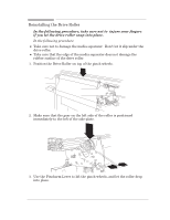
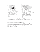
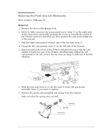
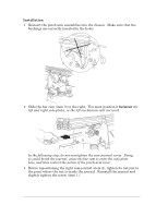
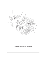
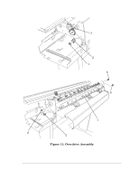
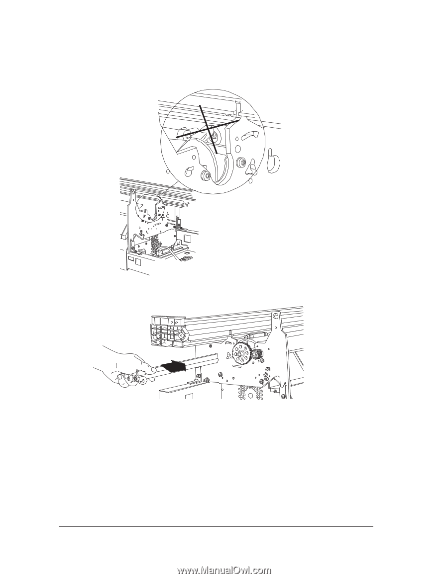
Installation 1. Reinsert the pinchĆarm assemblies into the chassis. Make sure that the bushings are correctly inserted in the holes. 2. Slide the bar cam (item 3) to the right. You must position it between the left and right sideĆplates, or the lift mechanism will not work. In the following step, do not overtighten the camĆjournal screw. Doing so could break the journal, cause the bar cam to enter the sideĆplate hole, and thus restrict the action of the pinchĆarm lever. 3. Before repositioning the right camĆjournal (item 2), tighten its nut just to the point where the nut is inside the journal. Reinstall the journal and slightly tighten the screw (item 1). 8-48 HP DesignJet 430, 450C and 455CA Printers Removal and Installation
-
 1
1 -
2
-
3
-
4
-
5
-
6
-
7
-
8
-
9
-
10
-
11
-
12
-
13
-
14
-
15
-
16
-
17
-
18
-
19
-
20
-
21
-
22
-
23
-
24
-
25
-
26
-
27
-
28
-
29
-
30
-
31
-
32
-
33
-
34
-
35
-
36
-
37
-
38
-
39
-
40
-
41
-
42
-
43
-
44
-
45
-
46
-
47
-
48
-
49
-
50
-
51
-
52
-
53
-
54
-
55
-
56
-
57
-
58
-
59
-
60
-
61
-
62
-
63
-
64
-
65
-
66
-
67
-
68
-
69
-
70
-
71
-
72
-
73
-
74
-
75
-
76
-
77
-
78
-
79
-
80
-
81
-
82
-
83
-
84
-
85
-
86
-
87
-
88
-
89
-
90
-
91
-
92
-
93
-
94
-
95
-
96
-
97
-
98
-
99
-
100
-
101
-
102
-
103
-
104
-
105
-
106
-
107
-
108
-
109
-
110
-
111
-
112
-
113
-
114
-
115
-
116
-
117
-
118
-
119
-
120
-
121
-
122
-
123
-
124
-
125
-
126
-
127
-
128
-
129
-
130
-
131
-
132
-
133
-
134
-
135
-
136
-
137
-
138
-
139
-
140
-
141
-
142
-
143
-
144
-
145
-
146
-
147
-
148
-
149
-
150
-
151
-
152
-
153
-
154
-
155
-
156
-
157
-
158
-
159
-
160
-
161
-
162
-
163
-
164
-
 165
165 -
 166
166 -
 167
167 -
 168
168 -
 169
169 -
 170
170 -
 171
171 -
 172
172 -
 173
173 -
 174
174 -
 175
175 -
176
-
177
-
178
-
179
-
180
-
181
-
182
-
183
-
184
-
185
-
186
-
187
-
188
-
189
-
190
-
191
-
192
-
193
-
194
-
195
-
196
-
197
-
198
-
199
-
200
-
201
-
202
-
203
-
204
-
205
-
206
-
207
-
208
 |
 |
8-48
Removal and Installation
HP DesignJet 430, 450C and 455CA Printers
Installation
1.
Reinsert the pinchĆarm assemblies into the chassis. Make sure that the
bushings are correctly inserted in the holes.
2.
Slide the bar cam (item 3) to the right. You must position it
between
the
left and right sideĆplates, or the lift mechanism will not work.
In the following step, do not overtighten the camĆjournal screw. Doing
so could break the journal, cause the bar cam to enter the sideĆplate
hole, and thus restrict the action of the pinchĆarm lever.
3.
Before repositioning the right camĆjournal (item 2), tighten its nut just to
the point where the nut is inside the journal. Reinstall the journal and
slightly tighten the screw (item 1).