HP 450c Service Manual - Page 134
DAMAGE THE CONNECTOR IN WHICH CASE IT WILL, Removing the FrontĆPanel Assembly
 |
View all HP 450c manuals
Add to My Manuals
Save this manual to your list of manuals |
Page 134 highlights
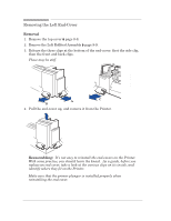
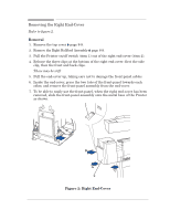
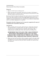
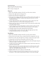
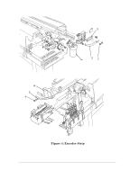
Removing the FrontĆPanel Assembly Removal 1. Remove the leftĆend cover ' page 8Ć10. 2. When removing the front panel, lift (but do not remove) the brown or black clip in the J1 connector before removing the front panel (FP) cable. You don't need to use any force at all. Be very careful when disconnecting the front panel connector from the Main PCA. If the cable is pulled too hard when removing the front panel it can damage the J1 front panel connector in the Main PCA which means that the complete electronics module has to be replaced. If you follow the instructions above, you will not damage the J1 connector: Remember that the clip must not be removed completely. If removed completely, the clip will be destroyed. Installation 1. When installing the front panel, pull the brown or black clip and insert the cable into the J1 connector. Once the cable is inside the connector, push the brown or black clip down to hold the cable in place. The conductive part (metallic part) of the cable must face the Main PCA. REMEMBER THAT PULLING THE CABLE WITHOUT RELEASING THE BROWN OR BLACK CLIP WILL DAMAGE THE CONNECTOR IN WHICH CASE IT WILL DESTROY THE COMPLETE ELECTRONICS MODULE. 2. Make sure that the Front Panel cable is properly routed by the clips inside the RightĆend cover and remains underneath the Spittoon at all times. If the Cable is not routed correctly, the Cutter Assembly can trap the cable and damage it. 8-12 HP DesignJet 430, 450C and 455CA Printers Removal and Installation
-
 1
1 -
2
-
3
-
4
-
5
-
6
-
7
-
8
-
9
-
10
-
11
-
12
-
13
-
14
-
15
-
16
-
17
-
18
-
19
-
20
-
21
-
22
-
23
-
24
-
25
-
26
-
27
-
28
-
29
-
30
-
31
-
32
-
33
-
34
-
35
-
36
-
37
-
38
-
39
-
40
-
41
-
42
-
43
-
44
-
45
-
46
-
47
-
48
-
49
-
50
-
51
-
52
-
53
-
54
-
55
-
56
-
57
-
58
-
59
-
60
-
61
-
62
-
63
-
64
-
65
-
66
-
67
-
68
-
69
-
70
-
71
-
72
-
73
-
74
-
75
-
76
-
77
-
78
-
79
-
80
-
81
-
82
-
83
-
84
-
85
-
86
-
87
-
88
-
89
-
90
-
91
-
92
-
93
-
94
-
95
-
96
-
97
-
98
-
99
-
100
-
101
-
102
-
103
-
104
-
105
-
106
-
107
-
108
-
109
-
110
-
111
-
112
-
113
-
114
-
115
-
116
-
117
-
118
-
119
-
120
-
121
-
122
-
123
-
124
-
125
-
126
-
127
-
128
-
 129
129 -
 130
130 -
 131
131 -
 132
132 -
 133
133 -
 134
134 -
 135
135 -
 136
136 -
 137
137 -
 138
138 -
 139
139 -
140
-
141
-
142
-
143
-
144
-
145
-
146
-
147
-
148
-
149
-
150
-
151
-
152
-
153
-
154
-
155
-
156
-
157
-
158
-
159
-
160
-
161
-
162
-
163
-
164
-
165
-
166
-
167
-
168
-
169
-
170
-
171
-
172
-
173
-
174
-
175
-
176
-
177
-
178
-
179
-
180
-
181
-
182
-
183
-
184
-
185
-
186
-
187
-
188
-
189
-
190
-
191
-
192
-
193
-
194
-
195
-
196
-
197
-
198
-
199
-
200
-
201
-
202
-
203
-
204
-
205
-
206
-
207
-
208
 |
 |