HP CP6015dn HP Color LaserJet CP6015 Series - User Guide - Page 215
Jam locations, Clear jams, WARNING - color laserjet fuser
 |
UPC - 883585363018
View all HP CP6015dn manuals
Add to My Manuals
Save this manual to your list of manuals |
Page 215 highlights
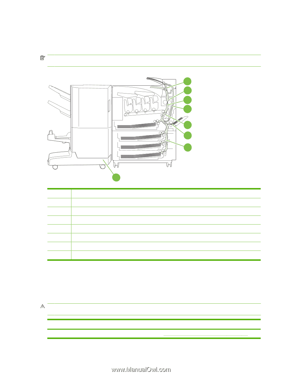
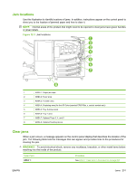
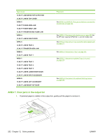
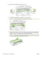
Jam locations Use this illustration to identify locations of jams. In addition, instructions appear on the control panel to direct you to the location of jammed paper and how to clear it. NOTE: Internal areas of the product that might need to be opened to clear jams have green handles or green labels. Figure 12-1 Jam locations 1 2 3 4 5 6 7 8 1 AREA 1: Output-bin area 2 AREA 2: Fuser area 3 AREA 3: Transfer area 4 AREA 4: Duplexing area (for the HP Color LaserJet CP6015dn, x, and xh models only) 5 AREA 5: Tray 2 pickup area 6 AREA 6: Tray 1 area 7 AREA 7: Optional Trays 3, 4, and 5 8 AREA 8: Optional finishing device Clear jams When a jam occurs, a message appears on the control-panel display that describes the location of the jam. The following table lists the messages that can appear and provides links to the procedures for clearing the jam. WARNING! To avoid electrical shock, remove any necklaces, bracelets, or other metal items before reaching into the inside of the product. Type of jam AREA 1: Procedure See AREA 1: Clear jams in the output bin on page 202. ENWW Jams 201
-
 1
1 -
2
-
3
-
4
-
5
-
6
-
7
-
8
-
9
-
10
-
11
-
12
-
13
-
14
-
15
-
16
-
17
-
18
-
19
-
20
-
21
-
22
-
23
-
24
-
25
-
26
-
27
-
28
-
29
-
30
-
31
-
32
-
33
-
34
-
35
-
36
-
37
-
38
-
39
-
40
-
41
-
42
-
43
-
44
-
45
-
46
-
47
-
48
-
49
-
50
-
51
-
52
-
53
-
54
-
55
-
56
-
57
-
58
-
59
-
60
-
61
-
62
-
63
-
64
-
65
-
66
-
67
-
68
-
69
-
70
-
71
-
72
-
73
-
74
-
75
-
76
-
77
-
78
-
79
-
80
-
81
-
82
-
83
-
84
-
85
-
86
-
87
-
88
-
89
-
90
-
91
-
92
-
93
-
94
-
95
-
96
-
97
-
98
-
99
-
100
-
101
-
102
-
103
-
104
-
105
-
106
-
107
-
108
-
109
-
110
-
111
-
112
-
113
-
114
-
115
-
116
-
117
-
118
-
119
-
120
-
121
-
122
-
123
-
124
-
125
-
126
-
127
-
128
-
129
-
130
-
131
-
132
-
133
-
134
-
135
-
136
-
137
-
138
-
139
-
140
-
141
-
142
-
143
-
144
-
145
-
146
-
147
-
148
-
149
-
150
-
151
-
152
-
153
-
154
-
155
-
156
-
157
-
158
-
159
-
160
-
161
-
162
-
163
-
164
-
165
-
166
-
167
-
168
-
169
-
170
-
171
-
172
-
173
-
174
-
175
-
176
-
177
-
178
-
179
-
180
-
181
-
182
-
183
-
184
-
185
-
186
-
187
-
188
-
189
-
190
-
191
-
192
-
193
-
194
-
195
-
196
-
197
-
198
-
199
-
200
-
201
-
202
-
203
-
204
-
205
-
206
-
207
-
208
-
209
-
 210
210 -
 211
211 -
 212
212 -
 213
213 -
 214
214 -
 215
215 -
 216
216 -
 217
217 -
 218
218 -
 219
219 -
 220
220 -
221
-
222
-
223
-
224
-
225
-
226
-
227
-
228
-
229
-
230
-
231
-
232
-
233
-
234
-
235
-
236
-
237
-
238
-
239
-
240
-
241
-
242
-
243
-
244
-
245
-
246
-
247
-
248
-
249
-
250
-
251
-
252
-
253
-
254
-
255
-
256
-
257
-
258
-
259
-
260
-
261
-
262
-
263
-
264
-
265
-
266
-
267
-
268
-
269
-
270
-
271
-
272
-
273
-
274
-
275
-
276
-
277
-
278
-
279
-
280
-
281
-
282
-
283
-
284
-
285
-
286
-
287
-
288
-
289
-
290
-
291
-
292
-
293
-
294
-
295
-
296
-
297
-
298
-
299
-
300
-
301
-
302
-
303
-
304
-
305
-
306
-
307
-
308
 |
 |