Yamaha A5000 Owner's Manual - Page 245
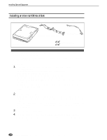
Attach the hard disk to the hard disk mount panel with the four hard disk installation
 |
View all Yamaha A5000 manuals
Add to My Manuals
Save this manual to your list of manuals |
Page 245 highlights
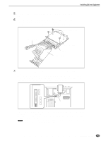
Installing Optional Equipment 5. Attach the hard disk to the hard disk mount panel with the four hard disk installation screws. 6. Connect the IDE cable (40-pin) and the power cable (long) to the hard disk unit. • Connect the center connector on the IDE cable to the hard disk. • The connectors are "keyed" so that they cannot be inserted the wrong way around. Hard disk installation screws Power cable (long) Hard disk mount panel IDE hard disk IDE cable (40-pin) 7. Connect the hard disk IDE cable (40-pin) to the connector on the A5000/A4000 circuit board. • Connect the short end of the flat cable from the hard disk (the flat, thin cable) to the corresponding con- nector on the sampler's main circuit board (marked "B" in the illustration below, "IDE CN4" on the circuit board itself). The connector is "keyed" so that it will only go in one way. B Short end • If a ZIP drive is also installed, the long end of the IDE flat cable from the hard disk should be connected to the ZIP drive connector (page 250). • If no ZIP drive is installed, secure the long end of the cable with the cable strap as shown in the step 10's illustration on the following page. • Damage can result if the loose end of the cable is allowed to come in contact with other internal circuitry. Be sure to secure the loose end of the cable with the cable strap. 245 q q q q q q q q q q q q q q q q q q q q q q q q q q q q q q q q q q q q q q q q q q q q q q q q q q q q q q q q q q q q q q A5000/A4000 • Appendix
-
 1
1 -
2
-
3
-
4
-
5
-
6
-
7
-
8
-
9
-
10
-
11
-
12
-
13
-
14
-
15
-
16
-
17
-
18
-
19
-
20
-
21
-
22
-
23
-
24
-
25
-
26
-
27
-
28
-
29
-
30
-
31
-
32
-
33
-
34
-
35
-
36
-
37
-
38
-
39
-
40
-
41
-
42
-
43
-
44
-
45
-
46
-
47
-
48
-
49
-
50
-
51
-
52
-
53
-
54
-
55
-
56
-
57
-
58
-
59
-
60
-
61
-
62
-
63
-
64
-
65
-
66
-
67
-
68
-
69
-
70
-
71
-
72
-
73
-
74
-
75
-
76
-
77
-
78
-
79
-
80
-
81
-
82
-
83
-
84
-
85
-
86
-
87
-
88
-
89
-
90
-
91
-
92
-
93
-
94
-
95
-
96
-
97
-
98
-
99
-
100
-
101
-
102
-
103
-
104
-
105
-
106
-
107
-
108
-
109
-
110
-
111
-
112
-
113
-
114
-
115
-
116
-
117
-
118
-
119
-
120
-
121
-
122
-
123
-
124
-
125
-
126
-
127
-
128
-
129
-
130
-
131
-
132
-
133
-
134
-
135
-
136
-
137
-
138
-
139
-
140
-
141
-
142
-
143
-
144
-
145
-
146
-
147
-
148
-
149
-
150
-
151
-
152
-
153
-
154
-
155
-
156
-
157
-
158
-
159
-
160
-
161
-
162
-
163
-
164
-
165
-
166
-
167
-
168
-
169
-
170
-
171
-
172
-
173
-
174
-
175
-
176
-
177
-
178
-
179
-
180
-
181
-
182
-
183
-
184
-
185
-
186
-
187
-
188
-
189
-
190
-
191
-
192
-
193
-
194
-
195
-
196
-
197
-
198
-
199
-
200
-
201
-
202
-
203
-
204
-
205
-
206
-
207
-
208
-
209
-
210
-
211
-
212
-
213
-
214
-
215
-
216
-
217
-
218
-
219
-
220
-
221
-
222
-
223
-
224
-
225
-
226
-
227
-
228
-
229
-
230
-
231
-
232
-
233
-
234
-
235
-
236
-
237
-
238
-
239
-
 240
240 -
 241
241 -
 242
242 -
 243
243 -
 244
244 -
 245
245 -
 246
246 -
 247
247 -
 248
248 -
 249
249 -
 250
250 -
251
-
252
-
253
-
254
-
255
-
256
-
257
-
258
-
259
-
260
-
261
-
262
-
263
-
264
-
265
-
266
-
267
-
268
-
269
-
270
-
271
-
272
-
273
-
274
-
275
-
276
-
277
-
278
-
279
-
280
-
281
-
282
-
283
-
284
-
285
-
286
-
287
-
288
-
289
-
290
-
291
-
292
-
293
-
294
-
295
-
296
 |
 |
