Brother International DCP1000 Service Manual
Brother International DCP1000 - DCP 1000 B/W Laser Manual
 |
UPC - 012502565796
View all Brother International DCP1000 manuals
Add to My Manuals
Save this manual to your list of manuals |
Brother International DCP1000 manual content summary:
- Brother International DCP1000 | Service Manual - Page 1
FACSIMILE EQUIPMENT SERVICE MANUAL MODEL: MFC6800/DCP1000 MFC9180/MFC9160 - Brother International DCP1000 | Service Manual - Page 2
This publication is a Service Manual covering the specifications, construction, theory of operation, and maintenance of the Brother facsimile equipment. It includes information required for field troubleshooting and repair--disassembly, reassembly, and lubrication--so that service personnel will be - Brother International DCP1000 | Service Manual - Page 3
shown below indicates compliance with the CDRH regulations and must be attached to laser products marketed in the United States. The label for Chinese products MANUFACTURED: JUNE 2001 C BROTHER CORP. (ASIA) LTD. BROTHER BUJI NAN LING FACTORY Gold Garden Industry, Nan Ling Village, Buji, Rong - Brother International DCP1000 | Service Manual - Page 4
CHAPTER 1 GENERAL DESCRIPTION CONTENTS 1.1 EQUIPMENT OUTLINE 1-1 1.1.1 External Appearance and Weight 1-1 1 1 2 Components 1-1 1.2 SPECIFICATIONS 1-2 - Brother International DCP1000 | Service Manual - Page 5
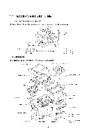
proper Machine (incl. drum unit & toner cartridge) In package Approx. Scanner top cover ADF & document tray ASSY Scanner base ASF Board access cover Main cover Gear drive unit Bottom plate aR Main PCB El) NCU PCB 1-1 Control panel ASSY Scanner mount Front cover Laser unit Heat-fixing unit - Brother International DCP1000 | Service Manual - Page 6
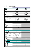
(Brother#1 Chart) Memory Transmission (ITU-T Chart) Broadcasting Manual Broadcasting Out-of-Paper Reception (Brother #1 Interface No Acceptable Media Card Slot N/A Analog Video Port N/A 1 -2 YL4-DCP DCP 1000 Laser (YL4) - 5.8"-8.5"/3.5"-8.5" 5"-14"/5"-14" Up to 30 16 characters x 2 - Brother International DCP1000 | Service Manual - Page 7
) (Manual Slot) Printer Driver YL4-FB(MFC) MFC 6800 Mono Laser (YL4) 600x600 up to 10 200 No 50 Windows GDI No No Yes LTR, LGL, A4, B5, A5, EXE N/A OHP, Envelopes, Organizer 64-105 g/m2 (17 - 28 Ib) N/A Win95/98/98SE/Me/2000Professional/ NT4.0VVS MacOS 8.5-9.1 YL4-DCP DCP 1000 (2/2) Mono Laser - Brother International DCP1000 | Service Manual - Page 8
Volume PBX Feature Transfer Method YL4-FB(wl Modem) MFC-9180 Laser (YL4) 14,400 (Fax) Approx. 6 (brother #1chart,MMR) G3 MH/MR/MMR 5.8"-8.5"/3.5"-8.5" 5"-14"/5"-14" Up (Brother#1 Chart) Broadcasting Manual Broadcasting Out-of-Paper Reception (ITU-T #1 Chart) Out-of-Paper Reception (Brother#1 - Brother International DCP1000 | Service Manual - Page 9
= For Windows Support OS version Printer Driver TWAIN Viewer Pop Up Menu OCR PC Fax Remote Setup PC Diagnostics Others For iMac/G3/G4 Support OS version Printer Driver TWAIN Viewer Pop Up Menu OCR PC Fax Remote Setup PC Diagnostics Others Print Others ACCESSORY Life / Yield Toner:TN-8000 Drum:DR - Brother International DCP1000 | Service Manual - Page 10
CHAPTER 2 INSTALLATION CONTENTS 2.1 INSTALLING THE UPDATE DATA TO THE FACSIMILE MACHINE 2-1 2.2 SETTING ID CODES TO FACSIMILE MACHINES CONNECTED TO A SINGLE PC VIA USB 2-3 - Brother International DCP1000 | Service Manual - Page 11
main PCB is replaced, then install the update program onto the flash ROM of the main PCB. The program installation requires a PC/AT-compatible the lock wires. (4) Connect the other end of the interface cable to the printer port of your computer and secure it with the two screws. (5) While pressing - Brother International DCP1000 | Service Manual - Page 12
the facsimile machine NOTE: The following is an installation procedure example on a PC that is running Windows 95/98. (1) Copy the update data and transfer press the ENTER key. During downloading, the machine beeps intermittently. Upon completion of the downloading, the machine beeps continuously. - Brother International DCP1000 | Service Manual - Page 13
■ Function Brother facsimile machines here. For models covered by this manual, set serial numbers given to individual the other end of the interface cable to the printer port of your PC and secure it with the run the ID setting utility. Follow the instructions shown on the PC's screen and enter the - Brother International DCP1000 | Service Manual - Page 14
CHAPTER 3 THEORY OF OPERATION CONTENTS 3.1 OVERVIEW 3.2 MECHANISMS 3.2.1 Scanner Mechanism 3.2.2 Laser Printing Mechanism 3.2.2.1 Paper pulling-in, registration, feeding, and ejecting mechanism 3.2.2.2 Print process mechanism 3.2.2.3 Heat-fixing mechanism 3.2.3 Sensors and Actuators 3.3 CONTROL - Brother International DCP1000 | Service Manual - Page 15
Speaker Printer data Fax data r ,- N , V V \ , V 1i V ,r ADF unit Scanner unit Laser printing unit Paper Low- and - ADF motor - CCD unit - -fixing processes _./ - Electrical charger - Laser unit (including the polygon motor) - Laser-sensitive drum - Developer roller - Transfer roller - - Brother International DCP1000 | Service Manual - Page 16
3.2 MECHANISMS The facsimile machine is classified into the following mechanisms: ■ SCANNER MECHANISM ■ LASER PRINTING MECHANISM ■ SENSORS AND ACTUATORS - ADF mechanism - Document scanning mechanism - Paper pulling-in and registration mechanism - Print process mechanism (consisting of charging, - Brother International DCP1000 | Service Manual - Page 17
rear sensor actuator 0 CCD HP sensor plate Document front sensor actuator 0 Document guide base tL I I II CCD rail CCD unit CCD flat cable SCANNER MECHANISM (Viewed from the front) SCANNER MECHANISM on 0 r-7 Paper pulling-in and registration mechanism Paper ejecting mechanism Heat - Brother International DCP1000 | Service Manual - Page 18
, ADF motor, and document front and rear sensors. The scanner unit consists of a scanner top cover, CCD unit, CCD drive mechanism, CCD HP sensor, and scanner base. For details about the sensors, refer to Subsection 3.2.3. Document guide base Document ejection roller ADF motor Document tray ADF - Brother International DCP1000 | Service Manual - Page 19
This scanner mechanism supports a dual scanning system. (1) If you set documents on the document guide base with their faces up and start the scanning operation, then the ADF motor rotates to pull in those documents into the ADF unit, starting from the top sheet to the bottom, page by page. Each - Brother International DCP1000 | Service Manual - Page 20
mechanism Pull-in roller 0 / Paper ejecting mechanism Paper ejection roller Laser-sensitive drum Heater roller \ Paper tray 'Paper ejection sensor actuator Pull-in roller drive gear Gear drive unit • • ; . ***,.... Drum drive gear Heater roller drive gear Paper ejection roller drive - Brother International DCP1000 | Service Manual - Page 21
drive gear Paper ejection roller drive gear .1401,1 ; Pull-in roller drive gear Intermediate gear Planetary gear system Clutch gear e. L Drum drive gear Gear drive unit Main motor The paper pulling-in and registration mechanism consists of the pull-in roller gear (incorporated in the auto - Brother International DCP1000 | Service Manual - Page 22
Toner augers Toner cartridge Toner sensor ( Paper Developer \ roller \\J O \ rj Toner supply roller Transfer roller Drum unit Laser-sensitive drum Cleaner roller Charger (Corona wire) Polygon minor Polygon motor Laser unit Cover glass Mirror Mirror The print process unit works with laser - Brother International DCP1000 | Service Manual - Page 23
mechanism Pressure roller (Paper ejection roller) Heater roller (including the FU lamp) Heat-fixing unit Paper N (Paper ejection sensor actuator) As the paper passes between the heater roller and the pressure roller in the heat-fixing unit, the heater roller fuses the toner on the paper. 3-9 - Brother International DCP1000 | Service Manual - Page 24
whether the document tray is closed. • Scanner open sensor which detects whether the scanner unit is closed. • Registration sensor which detects the the CCD unit is placed in the home position. • Toner sensor which detects whether there is toner or a toner cartridge is loaded. • Toner thermistor - Brother International DCP1000 | Service Manual - Page 25
(Relay PCB) CCD HP sensor CCD HP sensor plate (Laser unit) (Heat-fixing unit) Toner thermistor (on back of the toner sensor PCB) Toner sensor Registration sensor actuator Registration sensor (Main-fan PCB) Scanner open sensor actuator Scanner open sensor (Control panel PCB) Heater thermistor Paper - Brother International DCP1000 | Service Manual - Page 26
5-pin I 4-pin Laser Unit Laser diode Polygon motor Toner sensor PCB (Toner sensor) (Toner thermistor) 7 LASER PRINTING UNIT L _ , Main PCB UNITi Relay PCB i CCD unit 1 i (CCD motor) (CCD HP sensor) ISCANNEFTI, 7-pin !UNIT_ AC line Control panel PCB ASSY (Scanner open sensor) [ 12-pin - Brother International DCP1000 | Service Manual - Page 27
the Control Panel ASSY 4.1.7 Disassembly of the Scanner Unit 4.1.8 Front Cover 4.1.9 Relay PCB 4.1.10 Scanner Mount 4.1.11 Board Access Cover and Auto Sheet Feeder (ASF) 4.1.12 Heat-fixing Unit, FU Lamp, and Paper Ejection Sensor Actuator 4.1.13 Laser Unit and Toner Sensor PCB 4.1.14 Main PCB 4.1.15 - Brother International DCP1000 | Service Manual - Page 28
4.1.22 PCB Support and NCU PCB 4-54 4.1.23 Scanner Grounding Plate 4-55 4.1.24 EL (Eraser Lamp) Board 4-56 4.1.25 Harness Routing 4-57 4.1.26 Cleaning of High-voltage Contacts and Grounding Contacts 4-61 4.2 LUBRICATION 4-62 4.3 PERIODICAL REPLACEMENT PARTS 4-64 4.4 MTBF/MTTR 4-65 - Brother International DCP1000 | Service Manual - Page 29
When servicing the optical system of the laser printing unit, be careful not to place screwdrivers or other reflective objects in the path of the laser beam removed, they will become unusable and new gears will have to be put back in. (6) When using soldering irons and other heat-generating tools, - Brother International DCP1000 | Service Manual - Page 30
M3x8 1 Taptite, cup B IVI3x6 7 Taptite, cup B M3x6 1 Scanner top cover Guide plate CCD HP sensor plate Flat cable clamp Taptite, cup B M4x12 2 Taptite, pan B M3x10 1 Screw, pan (washer) M2.6x6DA 1 Laser unit Taptite, bind B M4x12 3 Main shield Taptite, cup S M3x6 2 Parallel - Brother International DCP1000 | Service Manual - Page 31
supply PCB (Low-voltage insulator sheet) Grounding wire Power inlet support High-voltage power supply PCB Duct Fan support Power supply shield Gear drive unit Main motor Gear support plate PCB support NCU shield NCU PCB Scanner grounding plate Taptite, cup S M3x6 2 Screw, pan (washer) M4x8DB - Brother International DCP1000 | Service Manual - Page 32
of an external telephone set if connected (Not shown below). (2) Remove - the paper support, - the paper tray, and - the drum unit (with the toner cartridge loaded) Drum unit (with toner cartridge loaded) Paper support Power cord Telephone line cord (Only for models w/ fax function) O pee Paper - Brother International DCP1000 | Service Manual - Page 33
Document guide base y Front cover (Scanner open sensor actuator) Front cover guides Separation rubber unit ADF support y laser unit Toner sensor PCB (NOTE 6) CI) (NOTE 7) Heat fixing unit -FU lamp NCU PCB i) Cr Scanner grounding ) Paper ejection plate sensor actuator 2 Gear drive unit - Brother International DCP1000 | Service Manual - Page 34
: Do not turn it to the left. Doing so will break the groove sections of the document guide base. Groove Latches /It o •-:7" ADF & document tray ASSY Document guide base Groove Guides 0 0 ■ Reassembling Notes • When setting the ADF cover back into place, fit its bottom edge under the stopper - Brother International DCP1000 | Service Manual - Page 35
4.1.2 ADF Components on the Upper ADF Chute Gear cover (1) As illustrated below, insert the tip of a flat screwdriver into the slot and lift up the right edge of the gear cover (arrow D) and move the gear cover to the front (arrow 0). Flat screwdriver \ T Gear cover Rib \ Latch Ribs Latch 4 - Brother International DCP1000 | Service Manual - Page 36
ADF chute Separation roller shaft Plastic retaining rings Document feed roller shaft Fitting the bushings into the cutouts provided in the ADF drive unit and setting the plastic retaining rings inside the upper ADF chute ----,_ Spring plate When setting the separation roller, take care not to - Brother International DCP1000 | Service Manual - Page 37
Note: After setting the rear end of the separation roller ASSY or document feed roller to the ADF drive unit, fit its bushing into the cutout provided in the ADF drive unit and then set the plastic retaining ring inside the upper ADF chute, as illustrated on the previous page. Separation - Brother International DCP1000 | Service Manual - Page 38
ADF thickness adjuster Lubricated with grease cz) Pressure roller springs Latches ADF thickness adjuster Correct position of the boss Guide Wrong position: Boss placed on the guide When setting the ADF thickness adjuster, do not put the boss provided on the underside of the adjuster on the - Brother International DCP1000 | Service Manual - Page 39
Upper ADF chute (6) Remove the two screws from the upper ADF chute. (7) Open the document tray (®). (8) From the underside of the document tray, release the two leftmost latches (C)) and then pull up the left end of the upper ADF chute (®). Taptite, cup B M3x8 (Rear) Upper ADF chute Latches - Brother International DCP1000 | Service Manual - Page 40
4.1.3 ADF Components on the Lower ADF Chute Document front and rear sensor actuators (1) Lift up the document front sensor actuator. Fully turn the document rear sensor actuator counterclockwise, then lift it up. Document rear sensor actuator Document front sensor actuator Lower ADF chute ( - Brother International DCP1000 | Service Manual - Page 41
clip. Each clip will snap out of the document ejection roller shaft. Document guide clip Lower ADF chute OO T Document ejection roller shaft (Rear) 0_ C)C 0 ejection roller. Boss Rear . 7 bushing Document ejection roller ADF drive unit (Rear) 0. 6 Pawled bushing Lower ADF chute 4-13 - Brother International DCP1000 | Service Manual - Page 42
the document ejection roller into the cutout of the ADF drive unit, orient the boss as illustrated on the previous page. Document pressure bar (7) Open the ADF & document tray ASSY. (8) Pull either of the front and rear supports of the document pressure bar outwards and remove the document pressure - Brother International DCP1000 | Service Manual - Page 43
then take its harness out of the cable guides and hooks. (11) Release the grounding wire from the ADF drive unit by removing the screw. (12) Remove the turn the planet gear counterclockwise (when viewed from the rear) ADF drive unit 0 Planet gear Grounding wire Lower ADF chute Taptite, cup B M3x8 - Brother International DCP1000 | Service Manual - Page 44
and release the ADF motor. NOTE: When using a screwdriver, take care not to scratch or damage gears on the ADF drive unit. Taptite, cup B M3x8 ADF drive unit flx n ADF motor 0 0 C' Lower ADF chute Screw, pan (s/p washer M3x6 C Reassembling Note: When setting the ADF motor, hook the non-screw - Brother International DCP1000 | Service Manual - Page 45
4.1.4 Document Tray Open Sensor and Document Stopper (1) Disconnect the document tray open sensor harness from the sensor. (2) Open the document tray. (3) Press the right and left latches of the document tray open sensor with the tip of a flat screwdriver as shown below and push it down. Document - Brother International DCP1000 | Service Manual - Page 46
the left-hand one.) Document tray O Scanner unit Front cover 0 tO .o . ':,', oo - C::, Scanner open lever Scanner springs Scanner mount Hooking the scanner spring onto the scanner mount and front cover Opening provided in the scanner mount Scanner spring Opening provided in the - Brother International DCP1000 | Service Manual - Page 47
(in the direction of arrow 0) and press the rear edge of the front cover inwards (arrow 0) to release its boss from the front cover connector. 0 Scanner unit Front cover connector O 3 Releasing the front cover from the front cover connector secured to the underside of the - Brother International DCP1000 | Service Manual - Page 48
the front right as shown below (arrow ®) so that the relay PCB can be fully seen. CAUTION: When putting the scanner unit on the scanner mount, take special care not to bend, wrinkle, or scratch the CCD flat cable or not to break the boss of the front cover (that - Brother International DCP1000 | Service Manual - Page 49
harness - Panel harness (8) Release the grounding wire (coming from the ADF drive unit) by removing the screw. (9) Lift up the scanner unit together with the document tray and control panel ASSY. Scanner unit Document sensor harness Document tray open sensor harness Cable clip Taptite, cup B M3x8 - Brother International DCP1000 | Service Manual - Page 50
the opening. (12) Lift up the document tray. Cable guide Cable sheath Latch Releasing the harnesses bound Cable sheath Opening Latch Cable binder Taptite, bind B M4x12 Panel harness Hinge Hinge Document tray Scanner unit O O. 0 C0 •0 0 0 o0 ADF motor harness Document sensor harness Document - Brother International DCP1000 | Service Manual - Page 51
below and remove it. (19) Remove the screw from the scanner open sensor PCB. Then the control panel ASSY is separated from the scanner unit. (For the disassembly procedure of the control panel ASSY and scanner unit, refer to Subsections 4.1.6 and 4.1.7, respectively.) (20) Remove the lever spring - Brother International DCP1000 | Service Manual - Page 52
the opening. Route the bound section through the cable guide so that the cable binder comes into contact with the cable guide as illustrated on page 4-22. Refer to Subsection 4.1.25 "Harness routing A." • When putting the scanner unit on the scanner mount, take special care not to bend, wrinkle, or - Brother International DCP1000 | Service Manual - Page 53
Control panel O 0 0 0 070 c, o OHO LCD 0 O FPC key Reinforcement plate Scanner open sensor Control panel PCB 6 Taptite, cup B M3x6 (4) As shown below, pull surface and control panel window with a soft cloth. • A new LCD is covered with a protection sheet. Before installing it, remove the protection sheet. 4 - Brother International DCP1000 | Service Manual - Page 54
4.1.7 Disassembly of the Scanner Unit The disassembly job of the scanner unit should be done in a clean room to prevent dust or dirt from getting into the scanner unit. (I) Remove the four screws from the scanner top cover. (2) Separate the scanner top cover from the scanner base. Scanner top cover - Brother International DCP1000 | Service Manual - Page 55
move the CCD unit to the right, lift up its front end and turn the CCD unit upright. The of the CCD unit. Right rear end of the CCD drive belt CCD drive belt CCD unit turned upright \ the underside of the CCD unit CCD drive belt Underside of the CCD unit turned upright CCD motor gear CCD - Brother International DCP1000 | Service Manual - Page 56
should be attached using new double-sided adhesive tape. (7) Lift up the CCD rail together with the CCD unit from the scanner base, then pull out the CCD rail. NOTE: When handling the CCD unit, do not touch the CCD PCB or glasses but hold the hatched sections as shown on the next - Brother International DCP1000 | Service Manual - Page 57
hatched sections are allowed to touch. 0 CCD unit CCD PCB (8) Remove the three screws and lift up the guide plate. (9) Remove the screw from the CCD HP sensor plate. Taptite, cup B M3x8 Guide plate CCD HP sensor plate I o Panel harness Flat cable clamp CCD HP sensor plate 4-29 Scanner base - Brother International DCP1000 | Service Manual - Page 58
-sided adhesive tape. • When reassembling the components inside the scanner unit, use screws (Taptite, cup B M3x8). Never use longer ones (e.g., M3x10). Using longer ones will bore a hole in the scanner base. • When installing the CCD drive belt to the scanner base, set its rear end within the range - Brother International DCP1000 | Service Manual - Page 59
and to the front (in the direction of arrow 0) to release the guide from boss "b," remove the guide in the direction of arrow O. Front cover Tab I Front cover guide Taptite cup B, M3x10 Boss "a" Front cover guide ≥Boss " O .0" 00 O Boss "b" Tab Scanner mount Boss "b" tt tt It Front cover - Brother International DCP1000 | Service Manual - Page 60
. (3) Lift up the relay PCB. Taptite, cup B M3x8 Relay (CCD/SEN) harness Grouding wire (To the main PCB) c Cable clip o Relay PCB Relay (ADF) harness Scanner mount Relay (CCD/PANEL) harness 4-32 - Brother International DCP1000 | Service Manual - Page 61
00 O (3) Remove the two screws from the scanner mount (4) Remove the scanner mount in the direction of the arrows. Relay (ADF) harness ° - Brother International DCP1000 | Service Manual - Page 62
4.1.11 Board Access Cover and Auto Sheet Feeder (ASF) (1) Remove the two screws from the board access cover. (Those screws secure also the ASF to the main cover.) (2) Push down the top of the board access cover to release the two latches from the main cover, then pull it to the rear. (3) Pull the - Brother International DCP1000 | Service Manual - Page 63
[Disassembling the ASF] I) Unhook the release lever spring. 2) Remove screw "a" and pull out the release lever. 3) Turn the release cam to the front and pull it out to the left. "a" Release lever (To be placed in front of the boss Setting the release lever IJ Boss Release lever spring Release - Brother International DCP1000 | Service Manual - Page 64
4) At the right end of the ASF, remove the screw from the grounding leaf spring R. (It is not necessary to remove the leaf spring.) Next pull out the pawled bushing R. At the left end of the ASF, remove the sector gear and its spring. Unlatch the pawled bushing L to the left and then remove it from - Brother International DCP1000 | Service Manual - Page 65
6) Turn the ASF upside down, then remove the registration sensor actuator. ASF 0 Viewed from the bottom Registration sensor actuator 4 -3 7 - Brother International DCP1000 | Service Manual - Page 66
7) There are two sets of pinch roller units. At each set, remove the leaf spring (in the order of 0 to shown below), pinch rollers, and pinch roller shaft. 8) At the left end of - Brother International DCP1000 | Service Manual - Page 67
10) Press the lock arm provided at the left inside of the ASF to the rear with a screwdriver, slide the ASF chute ASSY to the left, and take it out to the front. NOTE: To replace only the black film attached to the chute, do not remove the chute ASSY from the ASF. NOTE: A new chute and black film - Brother International DCP1000 | Service Manual - Page 68
thermistor harness from the EL (eraser lamp) board. (3) Remove the paper ejection sensor actuator from the bottom of the heat-fixing unit. Heat-fixing unit Taptite, cup B M4x 16 Relay (CCD/SEN) harness A Paper ejection sensor actuator c O Grounding wire Relay (CCD/PANEL) harness Brown heater - Brother International DCP1000 | Service Manual - Page 69
, be sure to insert the right edge of the wire into the folded fuse plate R. • A new heat-fixing unit will be provided with the heater thermistor harness being taped to the unit. When installing the unit, remove the tape. • Route the blue and brown heater wires on the main cover as illustrated in - Brother International DCP1000 | Service Manual - Page 70
above, just like the laser diode harness of the old laser unit. • On the underside of the laser unit, route the laser diode harness, polygon motor flat cable, and toner sensor harness as illustrated in Subsection 4.1.25, "Harness routing G." • Before putting the laser unit back into place, check - Brother International DCP1000 | Service Manual - Page 71
. The grounding wire will be released. Grouding wire (From the relay PCB) Main cover Relay (ADF) harness Main shield PCB support Low-voltage power harness Relay (CCD/SEN) harness Relay (CCD/PANEL) harness NCU harness a,, 00.-- "a" "c" "b" COm"b" "c" I III]] High-voltage power flat cable - Brother International DCP1000 | Service Manual - Page 72
■ Reassembling Notes • Be sure to route the harnesses and flat cable as illustrated in Subsection 4.1.25, "Harness routing D. III Make sure that the main motor harness is routed closest to the main PCB and that the relay (CCD/SEN) harness is routed after other harnesses are connected. Make sure that - Brother International DCP1000 | Service Manual - Page 73
CCD scanner area setting [Function code: 55] (Refer to CHAPTER 5, Subsections 5.3.11 and 5.3.10) Flash ROM or masked RO on the new main PCB? Flash ROM Masked ROM Install the update program onto the flash ROM. (For details about the installation procedure, refer to CHAPTER 2.) The "DOWNLOADING" is - Brother International DCP1000 | Service Manual - Page 74
4.1.15 Bottom Plate (1) Turn the machine upside down. (2) Remove the nine screws (four "x" and five "y") from the bottom plate, then lift it up. Bottom plate Scanner grounding plate (-> Main cover (placed upside down) "x": Taptite, cup S M3x6 "y": Taptite, bind B M4x12 4-46 - Brother International DCP1000 | Service Manual - Page 75
. (3) While pulling the right rear of the main cover (placed upside down) outwards to release the ON/OFF switch, lift up the power inlet support. (4) Remove screw "b." (5) Slightly lift up the low-voltage power supply PCB and disconnect the low-voltage power harness and heater harness (of the blue - Brother International DCP1000 | Service Manual - Page 76
-voltage power flat cable and route it as illustrated above. • Before reinstalling the high-voltage power supply PCB, check the high-voltage contacts for any toner particles, paper dust or dirt, and clean them out. 4-48 - Brother International DCP1000 | Service Manual - Page 77
fan harness from the PCB. (4) Take off the fan support by removing the screw. (5) Lift up the fan. Fan support Taptite, cup B M3x8 Taptite, bind B M4x12 Duct Main • Route the fan harness on the fan as illustrated above. • Put the fan back into place with the label side facing outwards and with its - Brother International DCP1000 | Service Manual - Page 78
4.1.19 Power Supply Shield (1) Remove the two screws and lift up the power supply shield. Power supply shield Low-voltage power harness Taptite, cup S M3x6 U-shaped cutout Opening Heater harness Main motor harness Solenoid harness II i Speaker harness High-voltage power flat cable Main - Brother International DCP1000 | Service Manual - Page 79
together with the spring. Speaker spring Ge°i, Speaker Solenoid harness Main motor harness Latch k Main cover (placed upside down) • Reassembling Notes • Put the speaker into place with its harness facing up. • Route the speaker harness through the latch together with the solenoid harness and - Brother International DCP1000 | Service Manual - Page 80
is removed. (2) Take out the heater harness from the cable guides provided on the top of the gear drive unit. (3) Remove the four screws and lift up the gear drive unit. Gear drive unit Setting the grounding plates and routing the heater harness Heater harness (of brown and blue wires) Main motor - Brother International DCP1000 | Service Manual - Page 81
, cup S M3x16 • Reassembling Notes • If the friction spring in the gear drive unit slips off, fit the straight end of the spring in the support hole of the gear drive unit as illustrated above. • When putting the gear drive unit back into the main cover, route the solenoid harness and main motor - Brother International DCP1000 | Service Manual - Page 82
the two screws and lift up the PCB support. Taptite, bind B M4x12 PCB support NCU harness 6 Main cover (placed upside down) (2) Remove the two screws and take off the NCU shield. (3) Remove the screw and take off the NCU PCB from the PCB support. (4) Disconnect the NCU harness. NCU harness PCB - Brother International DCP1000 | Service Manual - Page 83
will become unusable and a new one will have to be put back in. Taptite, cup B M3x8 Anti-static brush Scanner grounding plate I rL 1. I. 1. Main cover ■ Reassembling Notes • Before attaching a new anti-static brush onto the scanner grounding plate, wipe the surface of the attaching place with - Brother International DCP1000 | Service Manual - Page 84
Make sure that the EL harness is disconnected from the high-voltage power supply PCB. (Refer to Subsection 4.1.17.) (2) Make sure that the heat-fixing unit is removed. (3) Peel off the EL board from the main cover and clear adhesive tape if remaining. EL (eraser lamp) board Attaching a new EL board - Brother International DCP1000 | Service Manual - Page 85
harness Document tray open sensor harness U LI LI U 17; iii (Document sensor PCB) (Rear) (Cable guide) (Left) (Cable clip) Grounding wire (From the ADF drive unit (Relay PCB) (Scanner mount) (Cable guide) it Relay (ADF) harness Relay (CCD/PANEL) harness Grounding wire (To the main PCB - Brother International DCP1000 | Service Manual - Page 86
routing C: Relay (ADF) harness on the scanner mount Scanner mount Harness cover (Right) Relay (ADF) ) NCU harness (Tape) (PCB support) Polygon motor flat cable High-voltage power flat cable Relay (CCD/PANEL) harness Laser diode harness Toner sensor harness Main-fan harness Speaker harness - Brother International DCP1000 | Service Manual - Page 87
main cover (after the ASF is removed) Main cover Cable guides Relay (CCD/SEN) harness Relay (ADF) harness Opening Grounding wire Relay (CCD/PANEL) harness Harness routing F: Heater harness on the main cover (after the heat-fixing unit is removed) e EL harness • Blue heater wire Brown heater - Brother International DCP1000 | Service Manual - Page 88
diode harness, polygon motor flat cable, and toner sensor harness on the laser unit Toner sensor harness Laser diode harness Polygon motor flat cable (Laser unit) 0 0 Toner sensor harness 0 O (Front) Polygon motor flat cable Laser diode harness I farness routing H: Harnesses viewed from the - Brother International DCP1000 | Service Manual - Page 89
Contacts If any toner particles, paper dust or dirt are on the contacts, clean them out. This will ensure that power flows correctly to enable printing. Grounding contacts High-voltage contacts io 1 ------7 0 For transfer roller .z ."1..- Drum unit \ n I --- Gear drive unit \ 0 For cleaner - Brother International DCP1000 | Service Manual - Page 90
4.2 LUBRICATION Apply the specified lubricants to the lubrication points as shown below. Lubricant type (Manufacturer) Molykote EM-D110 (Dow Corning) Molykote PG662 (Dow corning.) FLOIL 951-P32 (Kanto Kasei Ltd.) Lubricant amount Rice-sized pinch of grease (6 mm3) (EMI) (Poi) (ED [ 1 ] - Brother International DCP1000 | Service Manual - Page 91
[ 2 ] ADF thickness adjuster Upper ADF chute PG1 (Rear) ADF thickness adjuster [ 3 ] CCD rail in the scanner unit Apply CD to 10 points on the CCD rail and move the CCD unit to the right and left ends of its travel. NOTE: Keep the CCD drive belt and other parts CFI) free from lubricant. (EL - Brother International DCP1000 | Service Manual - Page 92
appearance, replace them at regular intervals specified below. The replacement procedure is given in Section 4.1 "DISASSEMBLY/REASSEMBLY." Parts Name Heat-fixing unit Paper pull-in roller Separation pad ASSY Replacement Interval qty (Number of prints in terms of A4 size) 1 50,000 pages 1 50 - Brother International DCP1000 | Service Manual - Page 93
4.4 MTBF/MTTR The meantime between failures (MTBF) and meantime to repair (MTTR) of this machine are listed below. MTBF: At least 10,000 hours MTTR: Average 30 minutes per repair 4 -65 - Brother International DCP1000 | Service Manual - Page 94
LCD 5.3.7 Operational Check of Control Panel PCB 5.3.8 Sensor Operational Check 5.3.9 Fine Adjustment of Scanning Start/End Position 5.3.10 CCD Scanner Area Setting 5.3.11 EEPROM Customizing 5.3.12 Printout of the Equipment's Log Information 5.3.13 Display of the Equipment's Log Information 5.3.14 - Brother International DCP1000 | Service Manual - Page 95
5.1 ENTRY INTO THE MAINTENANCE MODE For machines w/ fax To make the equipment enter the maintenance mode, press the Menu, *, 2, 8, 6, and 4 keys in this order. k- Within 2 seconds -)I For machines w/o fax To make the equipment enter the maintenance mode, press the Menu, 0, 2, 8, 6, and 4 keys - Brother International DCP1000 | Service Manual - Page 96
5.3.5 (5-11) 5.3.6 (5-12) 5.3.7 (5-12) 32 Sensor Operational Check 5.3.8 (5-14) 54 Fine Adjustment of Scanning Start/End Position 55 CCD Scanner Area Setting 5.3.9 (5-15) 5.3.10 (5-16) 74 EEPROM Customizing 5.3.11 (5-16) 77 Printout of the Equipment's Log Information 5.3.12 (5-17) 80 - Brother International DCP1000 | Service Manual - Page 97
in the firmware switch tables in Appendix 2. The service personnel should instruct end users to follow the procedure given below. (1) 0 key Stop key For machines w/o fax I7O=Fo Copier. Printer •Scanner 2-Ardele 0 key Menu key Sort key brother DC P-1000 CC, t ixter Sae Sto. Exit CopMy ode. - Brother International DCP1000 | Service Manual - Page 98
5.3 DETAILED DESCRIPTION OF MAINTENANCE-MODE FUNCTIONS 5.3.1 EEPROM Parameter Initialization ■ Function The equipment initializes the parameters, user switches, and firmware switches registered in the EEPROM, to the initial values. Entering the function code 01 initializes all of the EEPROM areas, - Brother International DCP1000 | Service Manual - Page 99
5.3.2 Printout of Scanning Compensation Data ■ Function The equipment prints out the white and black level data for scanning compensation. ■ Operating Procedure Do not start this function merely after powering on the equipment but start it after carrying out a sequence of scanning operation. Unless - Brother International DCP1000 | Service Manual - Page 100
1999-01-30-21:19 40044708 dO 40044709 dO 4004470a dO 4004470d 50786000 10 10 10 1E1 10 10 10 10 10 10 1 10 4004470e 50786010 10 10 10 10 10 10 ICI 10 10 10 1 10 4004470f 50/86020 10 10 10 1El 10 10 10 18 18 10 50786030 10 10 10 10 10 1E1 18 113 10 10 10 40044712 50786040 7 77 7G 77 7Q 7, - Brother International DCP1000 | Service Manual - Page 101
5.3.3 ADF Performance Test ■ Function The equipment counts the documents fed by the automatic document feeder (ADF) and displays the count on the LCD for checking the ADF performance. ■ Operating Procedure (1) Set documents. (Allowable up to the ADF capacity.) The "DOC. READY" will appear on the LCD - Brother International DCP1000 | Service Manual - Page 102
5.3.4 Test Pattern 1 ■ Function This function, much like the copying function, prints out test pattern 1 to allow the service personnel to check for record data missing or print quality. ■ Operating Procedure Press the 0 and 9 keys in this order in the initial stage of the - Brother International DCP1000 | Service Manual - Page 103
5.3.5 Firmware Switch Setting and Printout [ A] Firmware switch setting ■ Function The facsimile equipment incorporates the following firmware switch functions which may be activated with the procedures using the control panel keys and buttons. The firmware switches have been set at the factory in - Brother International DCP1000 | Service Manual - Page 104
WSW No. WSW34 WSW35 WSW36 WSW37 WSW38 WSW39 WSW40 WSW41 WSW42 WSW43 WSW44 WSW45 WSW46 Firmware Switches (WSW01 through WSW46) Continued Function Function setting 12 Function setting 13 Function setting 14 Function setting 15 Function setting 16 in V. 34 mode Transmission speed setting in V. 34 mode - Brother International DCP1000 | Service Manual - Page 105
[ B ] Printout of firmware switch data ■ Function The equipment prints out the setting items and contents specified by the firmware switches. ■ Operating Procedure (1) Press the 1 key twice in the initial stage of the maintenance mode. The "PRINTING" will appear on the LCD. (2) The equipment prints - Brother International DCP1000 | Service Manual - Page 106
5.3.6 Operational Check of LCD • Function This function allows you to check whether the LCD on the control panel works normally. • Operating Procedure (1) Press the 1 and 2 keys in this order in the initial stage of the maintenance mode. The LCD shows the screen given at right. (2) For machines w/ - Brother International DCP1000 | Service Manual - Page 107
Contrast 32 = n9, 8Options Cop Copy For machines w/o fax Il b I r = \ - - \ N..Copier. Printer •Scanner LASER 2 2 3 3 Reports 13 fleCP Priht_ Reset 14 0 0GoScam-1-1r0, 04ID CPC9 ( O D Reduce Enlarge brother DCP-1000 Ratio Contrast Mode Stop/Fait Sort Copy Mode 0 CD Paper - Brother International DCP1000 | Service Manual - Page 108
Change the detecting conditions (e.g., insert paper through the document sensors or the registration sensor, open the scanner unit, jam paper at the paper outlet, remove the toner cartridge, move the CCD unit out of the home position, open the document tray), and then check that the indication on - Brother International DCP1000 | Service Manual - Page 109
5.3.9 Fine Adjustment of Scanning Start/End Position ■ Function This function allows you to adjust the scanning start/end position. ■ Operating Procedure (1) Press the 5 and 4 keys in this order in the initial stage of the maintenance mode. The "SCAN START ADJ." appears on the LCD. After two - Brother International DCP1000 | Service Manual - Page 110
the 5 key twice in the initial stage of the maintenance mode. The "SCANNER AREA SET" will appear on the LCD. The equipment checks and sets the to the initial stage of the maintenance mode. If any error is noted, the "SCANNER ERROR" will appear on the LCD. To return the equipment to the initial stage - Brother International DCP1000 | Service Manual - Page 111
.), indicating how many pages the equipment has been printed since produced 4) Drum count (in hex.), indicating how many times the drum has been rotated 5) Drum change count (in hex.), indicating how many times drum replacement has been made 6) Toner change count (in hex.), indicating how many times - Brother International DCP1000 | Service Manual - Page 112
has stored about the latest transmission) to the telephone line. It allows the service personnel to receive the transmission log of the user's equipment at a remote location and use it for analyzing problems arising in the user's equipment. ■ Operating Procedure (1) If the user's equipment has - Brother International DCP1000 | Service Manual - Page 113
5.3.16 Cancellation of the Memory Security Mode (Applicable to the European version w/ fax only) ■ Function This procedure can cancel the memory security mode. Use this procedure if the user forgets his/her password entered when setting the memory security mode so as not to exit from the memory - Brother International DCP1000 | Service Manual - Page 114
codes shown in the "MACHINE ERROR X X" message 6.1.2 Communications Errors 6.2 TROUBLESHOOTING 6.2.1 Introduction 6.2.2 Precautions 6.2.3 Checking prior to Troubleshooting 6.2.4 Troubleshooting Procedures [ 1 ] Control panel related [ 2 ] Telephone related [ 3 ] Communications related [ 4 ] Paper - Brother International DCP1000 | Service Manual - Page 115
To help the user or the service personnel promptly locate the cause of a problem (if any), the facsimile the LCD Messages on the LCD CHANGE DRUM SOON CHECK DOCUMENT Remove document, then press STOP KEY. Probable Cause The service life of the drum unit will expire soon. This message appears - Brother International DCP1000 | Service Manual - Page 116
is turned OFF before the document rear sensor is turned ON.) No drum unit is loaded. Even after paper pick-up operation, the registration sensor the toner temperature drops, the equipment will be automatically recovered from the error state. The scanner open sensor detects that the scanner unit is - Brother International DCP1000 | Service Manual - Page 117
Brother. PAPER JAM Open cover, then remove jammed paper. (These messages appear alternately.) PLS OPEN COVER SCANNER ERROR TONER EMPTY Open cover, then replace new toner cartridge. TONER (3) When the equipment is switched on or the scanner unit is opened and then closed, the registration sensor or - Brother International DCP1000 | Service Manual - Page 118
Cannot detect Beam Detect signal. ) ( 73 No toner cartridge loaded. ) ( 74 Toner empty. ) ( 75 In-casing temperature error. ) registration sensor has gone OFF, the paper ejection sensor still stays OFF.) ( Al Scanner unit opened. ) ( A2 Document too long to scan. ) ( A3 Document not - Brother International DCP1000 | Service Manual - Page 119
not returned to the home position. ) ( AF The CCD HP sensor sticks to ON, indicating that the CCD unit has stayed in the home position. ) ( B1 Dark level offset data error. ) ( B2 Gain control data error. ) • ( B3 Scan area left edge detection error. ) ( B4 - Brother International DCP1000 | Service Manual - Page 120
6.1.2 Communications Errors If a communications error occurs, the facsimile equipment ® emits an audible alarm (intermittent beeping) for approximately 4 seconds, 0 displays the corresponding error message, and ® prints out the transmission verification report if the equipment is in sending - Brother International DCP1000 | Service Manual - Page 121
■ Definition of Error Codes on the Communications List (1) Calling Code 1 10 10 10 11 11 11 11 11 11 11 Code 2 08 20 21 01 02 03 05 06 07 10 Causes Wrong number called. Retrieval file error. Image data entry error. No dial tone detected before start of dialing. Busy tone detected before dialing. - Brother International DCP1000 | Service Manual - Page 122
remote terminal. 32 14 The available memory space of the remote terminal is less than that required for reception of the confidential or relay broadcasting instruction. 6-8 - Brother International DCP1000 | Service Manual - Page 123
(4) Instructions received from the remote terminal [checking the NSC, DTC, NSS, and DCS] Code 1 40 40 Code 2 02 03 Causes Illegal coding system requested. Illegal recording - Brother International DCP1000 | Service Manual - Page 124
(6) ID checking Code 1 63 63 63 63 63 63 Code 2 01 02 03 04 05 06 Causes Password plus "lower 4 digits of telephone number" not coincident. Password not coincident. Polling ID not coincident. Entered confidential mail box ID uncoincident with the mail box ID. Relay broadcasting ID not coincident. - Brother International DCP1000 | Service Manual - Page 125
(9) Signal isolation Code 1 90 Code 2 01 90 02 Causes Unable to detect video signals and commands within 6 seconds after CFR is transmitted. Received PPS containing invalid page count or block count. (10) Video signal reception Code 1 AO Code 2 03 AO 11 AO 12 AO 13 AO 14 AO 15 AO - Brother International DCP1000 | Service Manual - Page 126
(11) General communications-related Code 1 BO BO BO BF BF BF Code 2 02 03 04 01 02 03 Causes Unable to receive the next-page data. Unable to receive polling even during turn-around transmission due to call reservation. PC interface error. Transmission canceled by pressing the Stop key (before - Brother International DCP1000 | Service Manual - Page 127
for ALT. ACh found. FED turned off during reception of CC data. Timeout waiting for turning off the CC. Retraining forced for problems not fixed in phase 2. Problem with S-sequence of HDX-resync. FED turned off in the S-sequence of HDX-resync. S-sequence finished before prediction in HDX-resync - Brother International DCP1000 | Service Manual - Page 128
3. Timeout waiting for S-Sbar in phase 3. Timeout waiting for S-Sbar in phase 3. Timeout waiting for S in phase 3. Training after TRN failure. Problem with S-sequence in phase 4. FED turned off in S-sequence in phase 4. S-sequence finished before prediction in phase 4. Timeout waiting for S-Sbar in - Brother International DCP1000 | Service Manual - Page 129
(14) Equipment error Code 1 FF FF Code 2 00 FF Causes Burn-in operation canceled by pressing the Stop key. Unrecoverable MODEM error. 6-15 - Brother International DCP1000 | Service Manual - Page 130
the troubleshooting procedures, so this section covers some sample problems. However, those samples will help service personnel pinpoint and repair other defective elements if he/she analyzes and examines them well. 6.2.2 Precautions Be sure to observe the following to prevent the secondary troubles - Brother International DCP1000 | Service Manual - Page 131
Power requirements Check that: (1) The power supply specified on the rating plate located on the bottom of the machine is used. The supply voltage stays within the rating ±10%. (2) Each voltage level on AC input lines and DC lines is correct. (3) All cables and harnesses are firmly connected. (4) - Brother International DCP1000 | Service Manual - Page 132
6.2.4 Troubleshooting Procedures [ 1 ] Control panel related Trouble (1) LCD shows nothing. (2) Control panel inoperative PCB and main PCB • Control panel PCB • FPC key • Main PCB [ 2] Telephone related Trouble (1) No phone call can be made. (2) Speed dialing or one-touch dialing will not work. - Brother International DCP1000 | Service Manual - Page 133
is transmitted. • Main PCB • NCU PCB Check: [ 4 ] Paper/document feeding related Trouble (1) Neither "COPY: PRESS COPY" nor "FAX: NO. & START" message appears although gears • Main PCB • ADF parts • ASF • Drum unit • Heat-fixing unit • Drive gear ASSY • Main PCB • Separation pad on the ASF 6-19 - Brother International DCP1000 | Service Manual - Page 134
4.1.21, page 4-52.) • Replace the toner cartridge. • Replace the drum unit. • Check the connection of the laser flat cable on the main PCB. • Replace the main PCB. • Replace the laser unit. • Replace the high-voltage power supply PCB. , At the scanner Check the following components: - CCD flat - Brother International DCP1000 | Service Manual - Page 135
Trouble (3) Light (4) Dark Action to be taken At the scanner Check the following components: - CCD unit - Main PCB At the printer side • Replace the toner cartridge with a new one and print 4 to 5 pages. If the problem persists, proceed to the next step. • Remove the toner cartridge and start - Brother International DCP1000 | Service Manual - Page 136
is returned to its home position. • Replace the toner cartridge. • Replace the drum unit. • Replace the heat-fixing unit. At the printer side • Clean the laser beam window (glass) on the laser unit. • Replace the laser unit. (7) Black and blurred horizontal stripes r vroo+.1.-1.A. Afrpso, K")44mr - Brother International DCP1000 | Service Manual - Page 137
Trouble (9) White vertical streaks (10) White horizontal stripes Action to be taken At the scanner Check the following components: - CCD unit At the printer side • Clean the laser beam window on the laser unit. • Replace the toner cartridge. • Replace the drum unit. At the printer side • Replace - Brother International DCP1000 | Service Manual - Page 138
the laser flat cable on the main PCB. • Replace the laser unit. At the printer side • Check that the equipment is placed on a flat surface. • Shake the toner cartridge horizontally. If the problem persists, replace it. • Clean the laser beam window (glass) on the laser unit. • Replace the laser unit - Brother International DCP1000 | Service Manual - Page 139
than 36 lb./m2). • Clean the toner sensors (LED and light-receiver). • Replace the toner cartridge. • Replace the drum unit. • Check the fitting of the heater thermistor. Replace the heat-fixing unit. • Replace the low-voltage power supply PCB. At the printer side • Instruct the user to use paper of - Brother International DCP1000 | Service Manual - Page 140
weight (less than 36 lb./m2). • Clean the toner sensors (LED and light-receiver). • Check the toner sensor harnesses. • Replace the toner cartridge. • Replace the drum unit. • Replace the high-voltage power supply PCB. At the printer side • Instruct the user to use paper of the recommended weight - Brother International DCP1000 | Service Manual - Page 141
of High-voltage Contacts and Grounding Contacts Grounding Contacts High-voltage Contacts ()For transfer roller z Drum unit ®For cleaner roller @For grid @For developer roller ©For corona wire Gear drive unit Main cover 0 • @@ @ © High-voltage j power supply PCB Heat-fixing unit 6-27 - Brother International DCP1000 | Service Manual - Page 142
EEPROM CUSTOMIZING CODES This function allows you to customize the EEPROM according to language, function settings, and firmware switch settings. ■ Operating Procedure (1) For machines w/ fax To make the machine enter the maintenance mode, press the Menu, *, 2, 8, 6, and 4 keys in this order. - Brother International DCP1000 | Service Manual - Page 143
■ EEPROM Customizing Codes List Versions U.S.A. CANADA AUSTRALIA NEW ZEALAND ASIA (SINGAPORE) Model DCP1000 MFC6800 0001 9001 0002 0002 0006 0006 0027 0027 0040 0040 Versions GERMANY U.K. FRANCE NORWAY BELGIUM NETHERLANDS SWITZERLAND IRELAND FINLAND DENMARK AUSTRIA SPAIN ITALY SOUTH - Brother International DCP1000 | Service Manual - Page 144
WSW No. WSW01 WSW02 WSW03 WSW04 WSW05 WSW06 WSW07 WSW08 WSW09 WSW10 WSW11 WSW12 WSW13 WSW14 WSW15 WSW16 WSW17 WSW18 WSW19 WSW20 WSW21 WSW22 WSW23 WSW24 WSW25 WSW26 WSW27 WSW28 WSW29 WSW30 WSW31 WSW32 WSW33 WSW34 WSW35 WSW36 WSW37 WSW38 WSW39 WSW40 WSW41 WSW42 WSW43 WSW44 WSW45 WSW46 Function Dial - Brother International DCP1000 | Service Manual - Page 145
ms 40 ms (for 16 PPS) 64 ms (at 106-ms intervals) 800 ms 850 ms 950 ms 600 ms 1: No 1: DP NOTE: In models supporting no pulse (DP) dialing mode (e.g., U.S.A. version), selector 7 takes no effect even if it may be set. • Selectors 1 and 2: Dial pulse generation mode These selectors set - Brother International DCP1000 | Service Manual - Page 146
• Selector 7: Switching between pulse (DP) and tone (PB) dialing, by the function switch This selector determines whether or not the dialing mode may be switched between the pulse (DP) and tone (PB) dialing by using the function switch. • Selector 8: Default dialing mode, pulse (DP) or tone (PB) - Brother International DCP1000 | Service Manual - Page 147
: Detection (Frequency only) * PABX: Private automatic branch exchange NOTE: Selectors 2 through 4, 6 and 7 are not applicable where no PABX is installed. • Selectors 1 and 5: CNG detection when sharing a modular wall socket with a telephone These selectors determine whether or not the equipment - Brother International DCP1000 | Service Manual - Page 148
• Selectors 6 and 7: Dial tone detection in PABX These selectors activate or deactivate the dial tone detection function which detects a dial tone when a line is connected to the PABX. Setting both of these selectors to "1" activates the dial tone detection function so that the equipment starts - Brother International DCP1000 | Service Manual - Page 149
ms : 80 ms : 110 ms : 250 ms : 500 ms NOTE: Selectors 5 through 8 are not applicable in those countries where no transfer facility is supported. • Selector 1: Earth function in transfer facility This selector determines whether or not the earth function is added to the transfer setting menu to be - Brother International DCP1000 | Service Manual - Page 150
before and after dialing 0 : Yes 1: No NOTE: Selectors 5 through 7 are not applicable in those countries where no busy tone detection is supported. • Selectors 1 through 3: 1st dial tone detection These selectors activate or deactivate the 1st dial tone detection function which detects the 1st - Brother International DCP1000 | Service Manual - Page 151
• Selectors 5 and 6: Busy tone detection in automatic sending mode These selectors determine whether or not the equipment automatically disconnects a line upon detection of a busy tone in automatic sending mode. Setting selector 6 to "0" ignores a busy tone so that the equipment does not disconnect - Brother International DCP1000 | Service Manual - Page 152
Selector No. 1 3 4 I 6 7 8 WSW06 (Pause key setting and 2nd dial tone detection) Function Setting and Specifications Pause key setting and 2nd dial tone detection Detection of 2nd dial tone No. of 2nd dial tone detection times M edial tone interrupt detecting No. 1 2 3 0 0 0 0 0 1 0 1 0 0 1 1 - Brother International DCP1000 | Service Manual - Page 153
by selectors 1 through 3 (Setting 101, 110, or 111). This function does not apply in those countries where no dial tone detection function is supported. • Selector 7: No. of 2nd dial tone detection times This selector sets the number of dial tone detection times required for starting dialing - Brother International DCP1000 | Service Manual - Page 154
dBm 0: 30 ms 1: 50 ms NOTE: Selectors 1 through 7 are not applicable in those countries where no dial tone or line current detection is supported, e.g., U.S.A. • Selectors 1 and 2: Frequency band range These selectors set the frequency band for the 1st dial tone and the busy tone (before dialing - Brother International DCP1000 | Service Manual - Page 155
-30 dBm -33 dBm -36 dBm -39 dBm -42 dBm NOTE: The WSW08 is not applicable in those countries where no dial tone detection is supported, e.g., U.S.A. • Selectors 1 through 3: 1st dial tone detection time length Upon detection of the 1st dial tone for the time length set by these selectors, the - Brother International DCP1000 | Service Manual - Page 156
. for US and Canada) : 140 sec. : 90 sec. : 35 sec. NOTE: Selectors 1 through 6 are not applicable in those models which do not support ECM. • Selector 1: Frame length selection Usually a single frame consists of 256 octets (1 octet = 8 bits). For communications lines with higher bit error rate - Brother International DCP1000 | Service Manual - Page 157
Selector No. 1 2 3 4 5 6 8 WSW10 (Protocol definition 2) Function Switching of DPS, following the CML ON/OFF Time length from transmission of the last dial digit to CML ON Time length from CML ON to CNG transmission Time length from CML ON to CED transmission (except for facsimile-to-telephone - Brother International DCP1000 | Service Manual - Page 158
Widens by 10 Hz 1: 400-600/400-600 ms 1: 175-440/175-440 ms 1: 100-1000/17-660 ms 1: 110-410/320-550 ms 1: 100-660/100-660 ms NOTE: WSW11 is not applicable in those countries where no busy tone detection is supported. NOTE: The setting of WSW11 is effective only when selectors 5 and 6 - Brother International DCP1000 | Service Manual - Page 159
Selector No. 1 2 3 4 5 6 7 8 WSW12 (Signal detection condition setting) Function Min. OFF time length of calling signal (Ci) Max. OFF time length of calling signal (Ci) Detecting time setting Delay Not used. Setting and Specifications No. 1 0 0 1 1 No. 3 0 0 1 1 No. 5 0 0 1 1 0: 2 0 : 1 : 0 : 1 - Brother International DCP1000 | Service Manual - Page 160
Selector No. 1 2 3 4 5 8 WSW13 (Modem setting) Function Cable equalizer Reception level Modem attenuator Setting and Specifications No. 1 2 00 : 01 : 10 : 11 : No. 3 4 00 : 01 : 10 : 11 : 0: 0 dB 0: 0 dB 0: 0 dB 0: 0 dB 0 km 1.8 km 3.6 km 5.6 km -43 dBm -47 dBm -49 dBm -51 dBm 1: 8 dB 1: 4 dB - Brother International DCP1000 | Service Manual - Page 161
: Fixed to 2 times 0 0 1 0 : Fixed to 3 times 0 0 1 1 : Fixed to 4 times 0 1 0 0 : 1 to 2 times 0101 : 0110 : 0111 : 1 to 3 times 1 to 4 times 1 to 5 times 1000 : 1001 : 1010 : 2 to 3 times 2 to 4 times 2 to 5 times 1011 : 1100 : 1101 : 2 to 6 times 1 to 10 times 2 to 10 times 1 1 1 0 : 3 to - Brother International DCP1000 | Service Manual - Page 162
times 1 : 3 times I 1 : 15 times 0: Redialing 1: No redialing NOTE: Selector 7 is not applicable in those countries where no busy tone detection is supported. • Selectors 1 through 6: Selection of redial interval and No. of redialings The equipment redials by the number of times set by selectors - Brother International DCP1000 | Service Manual - Page 163
Selector No. 1 2 3 6 7 8 WSW16 (Function setting 1) Function Not used. CCITT superfine recommendation Setting and Specifications 0: OFF 1: ON Not used. Max. document length limitation Stop key pressed during reception 0: 400 cm 1: 90 cm 0: Not functional 1: Functional • Selector 2: CCITT - Brother International DCP1000 | Service Manual - Page 164
Selector No. 1 2 3 4 5 6 7 8 WSW17 (Function setting 2) Function Off-hook alarm Not used. No. 1 0 0 1 Setting and Specifications 2 0 : No alarm 1 : Always valid X : Valid except when 'call reservation' is selected. Calendar clock type Not used. Non-ring reception Not used. 0: U.S.A. type 1: - Brother International DCP1000 | Service Manual - Page 165
Selector No. 1 2 3 4 5 6 7 8 WSW18 (Function setting 3) Function Setting and Specifications Not used. No. 2 3 Detection enabled time for CNG and no tone 0 0: 0 1: 1 0: 1 1: 40 sec. 0 sec. 5 sec. 80 sec. (No detection) Not used. Registration of station ID Tone sound monitoring 0: No. 7 0 - Brother International DCP1000 | Service Manual - Page 166
a higher one. • Selector 7: V. 34 mode This selector determines whether or not the equipment communicates with the remote station in the V. 34 mode when that station supports the V. 34 mode. 23 - Brother International DCP1000 | Service Manual - Page 167
WSW20 (Overseas communications mode setting) Selector No. 1 2 3 4 5 6 7 8 Function Setting and Specifications EP* tone prefix 0: OFF 1: ON Overseas communications mode (Reception) 0: 2100 Hz 1: 1100 Hz Overseas communications mode (Transmission) 0: OFF 1: Ignores DIS once. No. 4 5 Min. - Brother International DCP1000 | Service Manual - Page 168
selector to "0" allows the user to decide whether or not to interrupt the current call when a new call comes in. If Call Waiting Caller ID service is available in the area and the user subscribes to it, he/she can see information about his/her incoming call. • Selectors 5 through 8: Acceptable TCF - Brother International DCP1000 | Service Manual - Page 169
WSW23 (Communications setting) Selector No. Function Setting and Specifications 1 Starting point of training check (TCF) 0: From the head of a series of zeros 1: From any arbitrary point 2 Allowable training error rate 3 No. 2 3 00 : 01 : 10 : 11 : 0% 0.5% 1% 2% No. 4 5 4 Decoding error - Brother International DCP1000 | Service Manual - Page 170
Selector No. 1 2 3 4 5 8 WSW24 (TAD setting 2) Function Setting and Specifications Not used. Time length from CIVIL ON to start of pseudo ring backtone transmission Attenuator for playback of ICM/ OGM to the line (Selectable from the range of 0-15 dB) No. 3 4 00 : 01 : 10 : 11 : 4 sec. 3 sec. - Brother International DCP1000 | Service Manual - Page 171
Selector No. 1 2 3 4 5 7 8 WSW25 (TAD setting 3) Function Delay time for starting detection of voice signal Detection level for no voice signal Pause between paging number and PIN Not used. Setting and Specifications No. 1 2 00 0 1 : : 0 sec. 8 sec. 1 0 : 16 sec. 1 1 : 24 sec. No. 3 4 0 0 - Brother International DCP1000 | Service Manual - Page 172
Selector No. 1 2 3 4 5 6 8 WSW26 (Function setting 4) Function Setting and Specifications Not used. Dialing during document reading into the temporary memory in in-memory message transmission 0: Disabled 1: Enabled No. of CNG cycles to be detected No. 4 5 (when the line is connected via the - Brother International DCP1000 | Service Manual - Page 173
Not used. Detection of distinctive ringing pattern Setting and Specifications 0: TEL key 1: TEL/POLLING key 0: Yes 1: No 0: Yes 1: No Not used. Toner save mode 0: Yes 1: No NOTE: Selector 1 takes effect only in models/versions having a TEL key. NOTE: Selector 4 is applicable only to the - Brother International DCP1000 | Service Manual - Page 174
Selector No. 1 3I 4 6 7 8 WSW28 (Function setting 6) Function Transmission level of DTMF highband frequency signal Transmission level of DTMF low-band frequency signal Not used. Setting and Specifications No. 1 2 3 000 : 001 : 010 : 011 : 100 : 101 : 110 : 111 : No. 4 5 6 000 : 001 : 010 : 011 : - Brother International DCP1000 | Service Manual - Page 175
Not used. 0: OFF 1: ON NOTE: Selector 4 is applicable to the European version only. • Selector 4: Duty cycle control of pulsed current for the heat-fixing unit Setting this selector to "1" activates the duty cycle control that suppresses the rush current. The duty cycle is 10-ms ON and 20-ms OFF - Brother International DCP1000 | Service Manual - Page 176
of 90 ms long, then the equipment will interpret the short-OFF as OFF. • Selector 8: "CHANGE DRUM SOON" message This selector determines whether or not the "CHANGE DRUM SOON" message should appear on the LCD when the service life of the laser-sensitive drum in the laser unit will expire soon. 33 - Brother International DCP1000 | Service Manual - Page 177
Selector No. 1 4 5 6 7 8 WSW32 (Function setting 10) Function Setting and Specifications Not used. Default resolution Default contrast No. 5 6 0 0 : 0 1 : 1 0 : 1 1 : No. 7 8 0 X: 1 0 : 1 1 : Standard Fine Super fine Photo Automatic Super light Super dark • Selectors 5 and 6: Default - Brother International DCP1000 | Service Manual - Page 178
WSW34 (Function setting 12) Selector No. 1 3 4 5 6 7 8 Function Setting and Specifications Not used. No. of CNG cycles to be detected No. 4 5 (when the line is connected via the facsimile equipment in the FIT mode or via the external telephone in the 0 0 : 0.5 01 : 1 1 0 : 1.5 external TAD - Brother International DCP1000 | Service Manual - Page 179
WSW36 (Function setting 14) Selector No. 1 2 3 4 5 6 8 Function Setting and Specifications ECP* mode Recovery from inactive PC interface PC power-off recognition time Not used. Escape from phase C Lower limit of frequency to be ignored after detection of calling signals (Ci) 0: ON 0: Disabled - Brother International DCP1000 | Service Manual - Page 180
the stored 1st-page image data of an unsent document at the time of the subsequent in-memory message transmission only when recording paper or toner runs out. 37 - Brother International DCP1000 | Service Manual - Page 181
Selector No. 1 2 3 4 5 6 7 8 WSW38 (Function setting 16 in V. 34 mode) Function Setting of the equalizer Sending level of guard tone at phase 2 Stepping down the transmission speed at fallback each Automatic control of modem's EQM gain for proper transmission speed choice Redialing when a - Brother International DCP1000 | Service Manual - Page 182
Selector No. 1 I 4 5 I 8 WSW39 (Transmission speed setting in V. 34 mode) Function First transmission speed choice for fallback Last transmission speed choice for fallback Setting and Specifications No. 1 2 3 4 No. 5 6 7 8 0 0 0 0 : 2400 bps 0 0 0 1 : 4800 bps 0 0 1 0 : 7200 bps 0 0 1 1 : 9600 - Brother International DCP1000 | Service Manual - Page 183
Selector No. 1 2 3 8 WSW40 (Function setting 17 in V. 34 mode) Function Setting and Specifications Not used. Masking of symbol rate(s) Not masking No. 3 0 No. 4 0 No. 5 0 No. 6 0 No. 7 - No. 8 0 Masking 1 3429 symbols/sec 1 3200 symbols/sec 1 3000 symbols/sec 1 2800 symbols/sec - - Brother International DCP1000 | Service Manual - Page 184
effect only in V. 34 mode. NOTE: Selectors 1 through 3 are applicable only to models equipped with a flat-bed scanner. • Selectors 1 through 3: ON-duration of the fluorescent lamp built in the CCD unit If the scanning operation is started when the fluorescent lamp is off, then the lamp will come on - Brother International DCP1000 | Service Manual - Page 185
WSW42 (Function setting 18) Selector No. 1 2 3 4 5 8 Function Incoming mail server POP° Incoming mail server SMTP*2 Internet-FAX forward function JBIG*3 coding system Not used. Setting and Specifications 0: OFF 0: OFF 0: OFF 0: Disabled 1: ON 1: ON 1: ON 1: Enabled *1 POP: Post Office Protocol - Brother International DCP1000 | Service Manual - Page 186
ineffective 1 min. 3 min. 5 min. 10 min. 15 min. 20 min. 30 min. NOTE: WSW44 is applicable only to models equipped with a flat-bed scanner. • Selectors 6 through 8: Effective time length of the white level compensation data obtained beforehand If you set documents in the ADF and the document front - Brother International DCP1000 | Service Manual - Page 187
30 sec. 0 1 1 : 1 mm. 1 0 0 : 3 min. 1 0 1 : 5 min. 1 1 0 : 10 min. 1 1 1 : 30 min. NOTE: WSW45 is applicable only to models equipped with a flat-bed scanner. • Selectors 1 through 3: Delay time from when documents are set until the ADF starts drawing them in These selectors determine how long the - Brother International DCP1000 | Service Manual - Page 188
WSW46 (Monitor of PC ONIOFF state) Selector No. Function 1 2 Monitoring the PC ON/OFF state 3 Not used. 8 Setting and Specifications No. 1 2 0 0 : Disabled 0 1 : Monitor SELECT IN 1 0 : Monitor STROBE 1 1 : Monitor both SELECT IN and STROBE • Selectors 1 and 2: Monitoring the PC ONIOFF state - Brother International DCP1000 | Service Manual - Page 189
A. Main PCB (115) 2 3 4 5 6 7 8 RESET IC (=slice ,I0ov13992, - 0 -49891. .*,R,,1. 15 47 .,,, 71,: ,2 ,... , SYSTEM CLOCK ASIC 1 .5 0 SOO 04a. 6V R. ' S 4 8047F sot T RIM ev , t9nw7k1, 7f-47.770....a LASER CLOCK .,Cr 9, 4 re MO -L IT= r tIFS1 04 - - m 9.9, MGM. „„:, is F.,. . - Brother International DCP1000 | Service Manual - Page 190
A. Main PCB (2/5) 2 3 4 5 7 B 42 PIN FUE11171 PIN FLAII F614{FLUIN3J tN:l MSC, 622 22 1611 321 PI 2.0.9, R74 SI 1614 33) NC NC FrMit A30 Ale Al3 7020 Al3 Ale if 439 A19 li Ik 7019 419 FESS. 2626-2 IL 0.37 NC 220 94 PII4 F1•611171 PIII FUJITSU al 331 to IC Am 13 - Brother International DCP1000 | Service Manual - Page 191
TF633 - Brother International DCP1000 | Service Manual - Page 192
2 3 4 A. Main PCB (415) 7 B A *CM.. EUR x (12 B *CNS NCUI. -E t"- ..,- 12,191 1-11 --""M sov O424V ONOV • ISLU:M11 C OTC-1140A I. R2 II.0 NILO tgESO 41.4/94.0 711 - I*. SOVO ANALOG SW 1501n TSSOR r File r07414405.42, (S.4-40-3 ) CIV. OPEN 709. 6V Iv. MEMO R91 mo -FOSS - Brother International DCP1000 | Service Manual - Page 193
A. Main PCB (5/5) 2 3 4 77 I 5 7 B 0,05 LVPS 4sv Tn'amir-6 i 01' A F11.1 MMIER-02 532-2H -TfMi T,-Irft c- -0 261/ 0I5V 4-14 COMM ITO ISOM 616 an 1 1276 I 20 TF„ . a4 1(5 EGt PCB (ROM ass 'nal opp r• a+ain 7177n 11.107 an USTEIFEt-Fal Saab taint FEATB4-Cal TP1B7 B (MATER - Brother International DCP1000 | Service Manual - Page 194
B. NCU PCB (U.S.A., Canada) 2 3 V 4 5 6 4 4V OS .1 - 4910- 4 XX , XX (LINE] FS 7 FG s CN2 =I 05 RA-242V6-27 CN3 Le FL5R200FN D5 RA-3515-V5-2 L2 FL59200+6 F- 8 8 F. 7 (Exr) XX 4 XX3 .1 - 4910- 4 Lr3Y.YF,L..9.200R,1 US N/A AJ2 AKI Fe 100100 21 I 0i 2 W- 0 I CUA2- SH- 1240Z - Brother International DCP1000 | Service Manual - Page 195
ASSY 1 JP3 C23 CC153 CC682 NOT ASSY C0153 CC682 NOT ASSY CC153 CC582 NOT ASSY CHI R9 NOT ASSY 100s1/2W I3900/2W NOT ASSY 1000./2W I390.0/2W NOT ASSY 100f1/2W I3900/2W Soy SOV 50V FG D P1 P2 B12B - PHK BBB -PH -K 6138 - PHK NOT ASSY B1 ,3B - Brother International DCP1000 | Service Manual - Page 196
-1- 111610%17,u 6B5 KF PLS REF sl O2R11/1:9WC 24 3 PLS R32 SOF +5V • 062 91Y640 or S1Z660 DO ERAI5-04 IPH4 ITLP627 RS v, 20 1000 •M; OAST Q5 JWI 61 I 1 IPH3 - 3 J P4 S V R10 CR1 A5X-24E-907 11 . 4CML D4 133120 +24V R5 10K 1/4W9 01 ERA)5-04 R2B 470 - R2 - Brother International DCP1000 | Service Manual - Page 197
1. 2 3 17 4 5 6 +24V LS O 33 155120 ..m20(5) Jr11715/A24(101 CML F& Not Assy CR1 SH-1240Z C4 50V 2.2I C10 30 A NC rl= Ta 2 La Lb 4 Tb 5 L2 ,A4(5) Ai RA-242MS uki23 (ie) +24V 4329 C22 Not May I oi I 03)M CP2 SP2 • 0 9.1 / N.R1 081 ^2 • C23 Not Assy CSfi T1 BT-6 R11333 160 - Brother International DCP1000 | Service Manual - Page 198
ASSY ADRS. ZNR1 SP2 CR2 Q5 D3 JW15 JW29 JW31 JW43 PC1 R4 JW6;JW11 ZD1:ZD2 R1 R2 R9 R11 R12 R13 R22 C1 C10 C11 C12 C13 CN3 CN5 CN4 Q2 R7 R8:R30 R14 R32;R36 R34;R35 R37 C8 C9:C19 C20:C21 C24 JW35;JW38;L5;L6:L7:L8 D4D5 JW28 #2 R33 C18 JW9:JW34;JW39 Q3 R10 R17 JW2:JW3 L1 NCU B53K479 ASSY ASIA W/O TEL - Brother International DCP1000 | Service Manual - Page 199
C. Control Panel PCB 2 I 3 4 5 6 +242 n*9 9 COE Aff4t.htt.i2F.R. - t •B CHI r 4242 ,- - LE A d- ci BM- PH- K- 5 50103 1/4W I I me_ DTC1 .4,AJA I 9' K . I KIM5eM G5 1 OTC114YUA W.VA.II*3BO6 ELR IOCN1. C1.0. Pe. R22. 214- 2445 3 ,29 Itahla0170,Ix 1.1 , zt 452 CN3 KI0) 6 KI1 - Brother International DCP1000 | Service Manual - Page 200
LIVE NEUTRAL F1 F2 L1 U • %-t NTC • CN2 3 vv 4-1 N < R20 N • 0 • T1 D101 +0 + 9 U (-1 7 O 0 a R19 C10 N 4 co 02 0) U • • • •- FG C7 D7 R7 R6 D4 tO 0a ) Ct PC1 N ti a D102 D103 D3 R10 CO U • I I C15 R22 R21 a 0-- - cn 4-1 a a IC101 In In 4-1 4-1 Cr - Brother International DCP1000 | Service Manual - Page 201
-- ^ Fl LIVE NEUTRAL E 'A N F2 N-4 N • L2 Li NTC1 / / / / / 0.1 U a(,) .O v 0 T1 • CN2 3 vv N " al N Iaa-- 0(I R20 U U Crl CU N R22 R21 CC • D101 IOT) + cl O 0 4 vi (_) O-4 / o , o , a -, N a RI N , cc cn N , a N. N , a N , a ID Na, N Uco - M 1_4 01 a - -)- l - Brother International DCP1000 | Service Manual - Page 202
F F2 LIVE L2 Li CN2 3 V NEUTRAL NTC1 AL 1 Z3 • +. Cl ru _ 4, 01 - R19 O to O V a2 ti • • C10 D7 R7 R6 04 4 a,) D-• • • • II C7 U 02 01 U 01 CC (13 O PC1 C N D3 R10 a) U N tf) U R20 R22 R21 T1 0101 cr, 0 U 0 4 , N0 O CC CC • 0102 IC101 D103 0 U O ,r4 CU - Brother International DCP1000 | Service Manual - Page 203
- Brother International DCP1000 | Service Manual - Page 204
rOG - RR I IOTRA4TA rs RSV '' CIO '. led 22 7, C19/. Rig RIO Fm MA, Rd 213 200 f9D 5f O ibV Rid 29 RDV 0 301-F80E-• vw XP.0 BCtng Had czoa 24PET T T >'CtleC7, 35.! 2W2 aRlR-~ID~A 2 3 4 5 6 I CR5000 7 a
-
 1
1 -
 2
2 -
 3
3 -
 4
4 -
 5
5 -
 6
6 -
 7
7 -
8
-
9
-
10
-
11
-
12
-
13
-
14
-
15
-
16
-
17
-
18
-
19
-
20
-
21
-
22
-
23
-
24
-
25
-
26
-
27
-
28
-
29
-
30
-
31
-
32
-
33
-
34
-
35
-
36
-
37
-
38
-
39
-
40
-
41
-
42
-
43
-
44
-
45
-
46
-
47
-
48
-
49
-
50
-
51
-
52
-
53
-
54
-
55
-
56
-
57
-
58
-
59
-
60
-
61
-
62
-
63
-
64
-
65
-
66
-
67
-
68
-
69
-
70
-
71
-
72
-
73
-
74
-
75
-
76
-
77
-
78
-
79
-
80
-
81
-
82
-
83
-
84
-
85
-
86
-
87
-
88
-
89
-
90
-
91
-
92
-
93
-
94
-
95
-
96
-
97
-
98
-
99
-
100
-
101
-
102
-
103
-
104
-
105
-
106
-
107
-
108
-
109
-
110
-
111
-
112
-
113
-
114
-
115
-
116
-
117
-
118
-
119
-
120
-
121
-
122
-
123
-
124
-
125
-
126
-
127
-
128
-
129
-
130
-
131
-
132
-
133
-
134
-
135
-
136
-
137
-
138
-
139
-
140
-
141
-
142
-
143
-
144
-
145
-
146
-
147
-
148
-
149
-
150
-
151
-
152
-
153
-
154
-
155
-
156
-
157
-
158
-
159
-
160
-
161
-
162
-
163
-
164
-
165
-
166
-
167
-
168
-
169
-
170
-
171
-
172
-
173
-
174
-
175
-
176
-
177
-
178
-
179
-
180
-
181
-
182
-
183
-
184
-
185
-
186
-
187
-
188
-
189
-
190
-
191
-
192
-
193
-
194
-
195
-
196
-
197
-
198
-
199
-
200
-
201
-
202
-
203
-
204
 |
 |
FACSIMILE
EQUIPMENT
SERVICE
MANUAL
MODEL:
MFC6800/DCP1000
MFC9180/MFC9160