Brother International DCP1000 Service Manual - Page 49
drive
 |
UPC - 012502565796
View all Brother International DCP1000 manuals
Add to My Manuals
Save this manual to your list of manuals |
Page 49 highlights
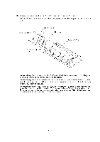
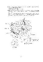
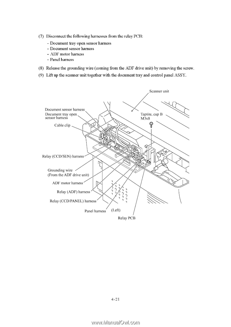
(7) Disconnect the following harnesses from the relay PCB: - Document tray open sensor harness - Document sensor harness - ADF motor harness - Panel harness (8) Release the grounding wire (coming from the ADF drive unit) by removing the screw. (9) Lift up the scanner unit together with the document tray and control panel ASSY. Scanner unit Document sensor harness Document tray open sensor harness Cable clip Taptite, cup B M3x8 Relay (CCD/SEN) harness O Grounding wire (From the ADF drive unit) ADF motor harness Relay (ADF) harness Relay (CCD/PANEL) harness \ Panel harness (Left) Relay PCB 4-21
-
 1
1 -
2
-
3
-
4
-
5
-
6
-
7
-
8
-
9
-
10
-
11
-
12
-
13
-
14
-
15
-
16
-
17
-
18
-
19
-
20
-
21
-
22
-
23
-
24
-
25
-
26
-
27
-
28
-
29
-
30
-
31
-
32
-
33
-
34
-
35
-
36
-
37
-
38
-
39
-
40
-
41
-
42
-
43
-
 44
44 -
 45
45 -
 46
46 -
 47
47 -
 48
48 -
 49
49 -
 50
50 -
 51
51 -
 52
52 -
 53
53 -
 54
54 -
55
-
56
-
57
-
58
-
59
-
60
-
61
-
62
-
63
-
64
-
65
-
66
-
67
-
68
-
69
-
70
-
71
-
72
-
73
-
74
-
75
-
76
-
77
-
78
-
79
-
80
-
81
-
82
-
83
-
84
-
85
-
86
-
87
-
88
-
89
-
90
-
91
-
92
-
93
-
94
-
95
-
96
-
97
-
98
-
99
-
100
-
101
-
102
-
103
-
104
-
105
-
106
-
107
-
108
-
109
-
110
-
111
-
112
-
113
-
114
-
115
-
116
-
117
-
118
-
119
-
120
-
121
-
122
-
123
-
124
-
125
-
126
-
127
-
128
-
129
-
130
-
131
-
132
-
133
-
134
-
135
-
136
-
137
-
138
-
139
-
140
-
141
-
142
-
143
-
144
-
145
-
146
-
147
-
148
-
149
-
150
-
151
-
152
-
153
-
154
-
155
-
156
-
157
-
158
-
159
-
160
-
161
-
162
-
163
-
164
-
165
-
166
-
167
-
168
-
169
-
170
-
171
-
172
-
173
-
174
-
175
-
176
-
177
-
178
-
179
-
180
-
181
-
182
-
183
-
184
-
185
-
186
-
187
-
188
-
189
-
190
-
191
-
192
-
193
-
194
-
195
-
196
-
197
-
198
-
199
-
200
-
201
-
202
-
203
-
204
 |
 |
(7)
Disconnect
the
following
harnesses
from
the
relay
PCB:
-
Document
tray
open
sensor
harness
-
Document
sensor
harness
-
ADF
motor
harness
-
Panel
harness
(8)
Release
the
grounding
wire
(coming
from
the
ADF
drive
unit)
by
removing
the
screw.
(9)
Lift
up
the
scanner
unit
together
with
the
document
tray
and
control
panel
ASSY.
Scanner
unit
Document
sensor
harness
Document
tray
open
sensor
harness
Cable
clip
Relay
(CCD/SEN)
harness
Grounding
wire
(From
the
ADF
drive
unit)
ADF
motor
harness
Relay
(ADF)
harness
Relay
(CCD/PANEL)
harness
\
Panel
harness
O
(Left)
Relay
PCB
4-21
Taptite,
cup
B
M3x8