Brother International DCP1000 Service Manual - Page 56
replacement
 |
UPC - 012502565796
View all Brother International DCP1000 manuals
Add to My Manuals
Save this manual to your list of manuals |
Page 56 highlights
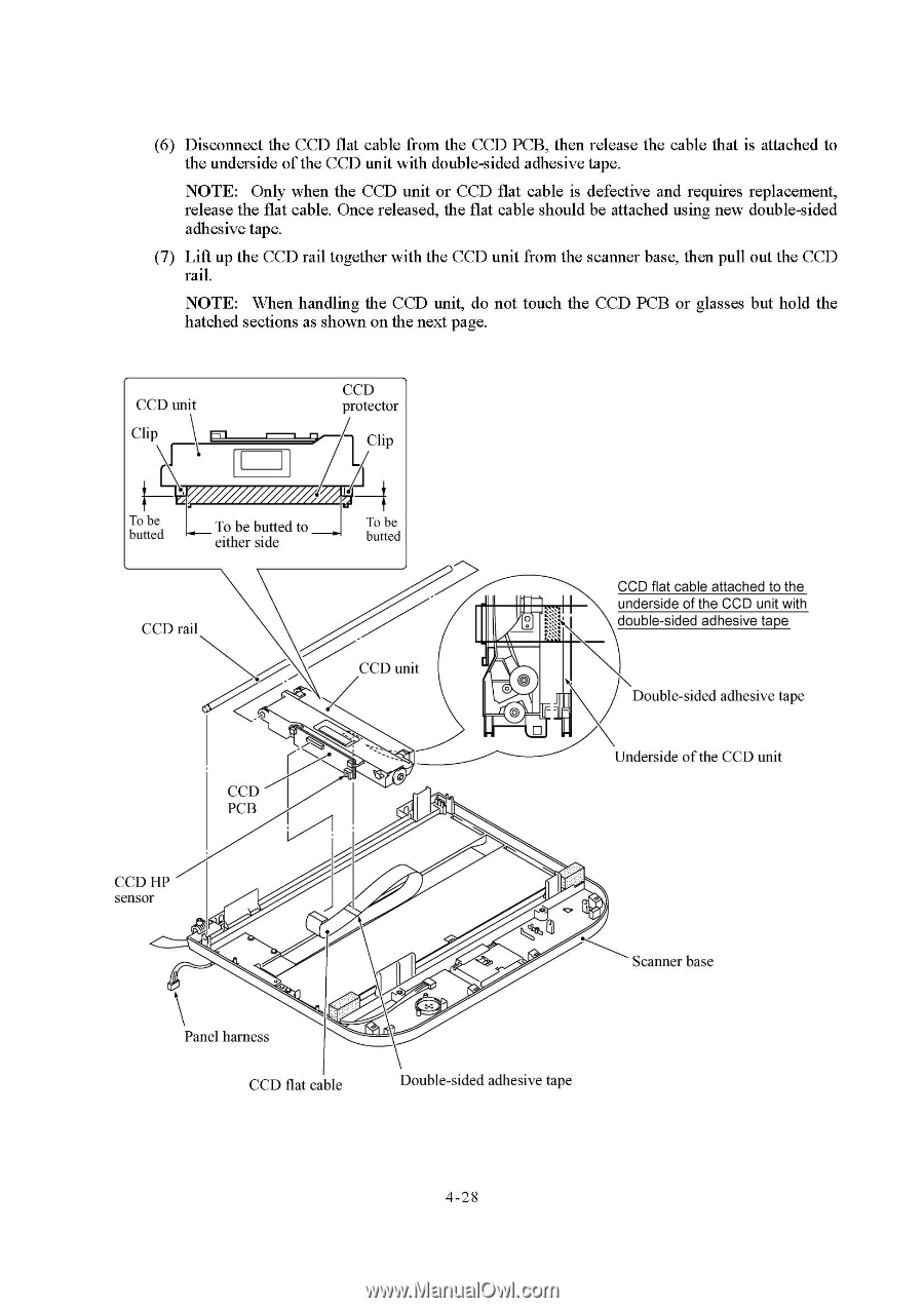
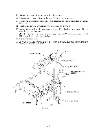
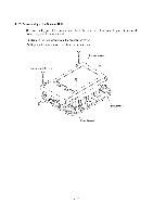
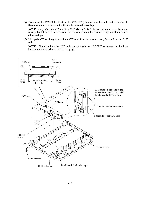
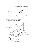
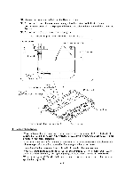
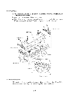
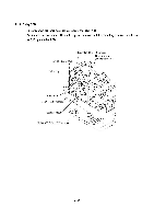
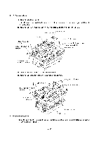
(6) Disconnect the CCD flat cable from the CCD PCB, then release the cable that is attached to the underside of the CCD unit with double-sided adhesive tape. NOTE: Only when the CCD unit or CCD flat cable is defective and requires replacement, release the flat cable. Once released, the flat cable should be attached using new double-sided adhesive tape. (7) Lift up the CCD rail together with the CCD unit from the scanner base, then pull out the CCD rail. NOTE: When handling the CCD unit, do not touch the CCD PCB or glasses but hold the hatched sections as shown on the next page. CCD unit Clip CCD protector Clip To butbtedeI To be butted to either side To be butted CCD rail CCD unit r0 CCD PCB CCD flat cable attached to the underside of the CCD unit with 0 double-sided adhesive tape Double-sided adhesive tape Underside of the CCD unit CCD HP sensor Scanner base Panel harness CCD flat cable Double-sided adhesive tape 4-28
-
 1
1 -
2
-
3
-
4
-
5
-
6
-
7
-
8
-
9
-
10
-
11
-
12
-
13
-
14
-
15
-
16
-
17
-
18
-
19
-
20
-
21
-
22
-
23
-
24
-
25
-
26
-
27
-
28
-
29
-
30
-
31
-
32
-
33
-
34
-
35
-
36
-
37
-
38
-
39
-
40
-
41
-
42
-
43
-
44
-
45
-
46
-
47
-
48
-
49
-
50
-
 51
51 -
 52
52 -
 53
53 -
 54
54 -
 55
55 -
 56
56 -
 57
57 -
 58
58 -
 59
59 -
 60
60 -
 61
61 -
62
-
63
-
64
-
65
-
66
-
67
-
68
-
69
-
70
-
71
-
72
-
73
-
74
-
75
-
76
-
77
-
78
-
79
-
80
-
81
-
82
-
83
-
84
-
85
-
86
-
87
-
88
-
89
-
90
-
91
-
92
-
93
-
94
-
95
-
96
-
97
-
98
-
99
-
100
-
101
-
102
-
103
-
104
-
105
-
106
-
107
-
108
-
109
-
110
-
111
-
112
-
113
-
114
-
115
-
116
-
117
-
118
-
119
-
120
-
121
-
122
-
123
-
124
-
125
-
126
-
127
-
128
-
129
-
130
-
131
-
132
-
133
-
134
-
135
-
136
-
137
-
138
-
139
-
140
-
141
-
142
-
143
-
144
-
145
-
146
-
147
-
148
-
149
-
150
-
151
-
152
-
153
-
154
-
155
-
156
-
157
-
158
-
159
-
160
-
161
-
162
-
163
-
164
-
165
-
166
-
167
-
168
-
169
-
170
-
171
-
172
-
173
-
174
-
175
-
176
-
177
-
178
-
179
-
180
-
181
-
182
-
183
-
184
-
185
-
186
-
187
-
188
-
189
-
190
-
191
-
192
-
193
-
194
-
195
-
196
-
197
-
198
-
199
-
200
-
201
-
202
-
203
-
204
 |
 |