Brother International DCP1000 Service Manual - Page 81
illustration
 |
UPC - 012502565796
View all Brother International DCP1000 manuals
Add to My Manuals
Save this manual to your list of manuals |
Page 81 highlights
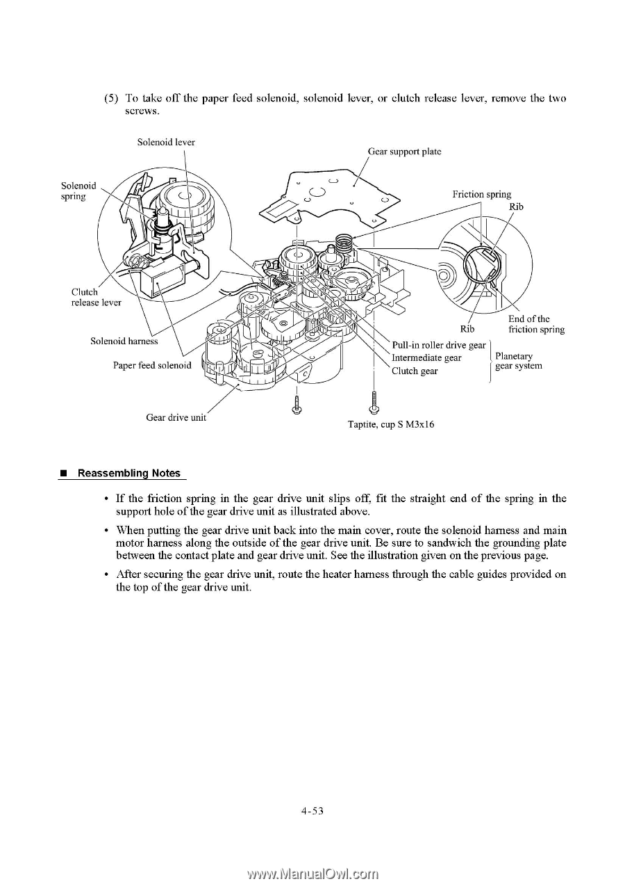
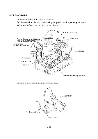
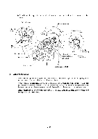
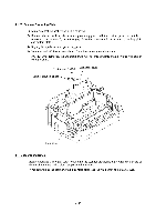
(5) To take off the paper feed solenoid, solenoid lever, or clutch release lever, remove the two screws. Solenoid lever Gear support plate Solenoid spring it Friction spring Rib Clutch release lever Solenoid harness Paper feed solenoid i 1 ..- 'A,- - -I r,--) (Ail) J), End of the Rib friction spring Pull-in roller drive gear Intermediate gear Clutch gear Planetary gear system Gear drive unit Taptite, cup S M3x16 • Reassembling Notes • If the friction spring in the gear drive unit slips off, fit the straight end of the spring in the support hole of the gear drive unit as illustrated above. • When putting the gear drive unit back into the main cover, route the solenoid harness and main motor harness along the outside of the gear drive unit. Be sure to sandwich the grounding plate between the contact plate and gear drive unit. See the illustration given on the previous page. • After securing the gear drive unit, route the heater harness through the cable guides provided on the top of the gear drive unit. 4-53
-
 1
1 -
2
-
3
-
4
-
5
-
6
-
7
-
8
-
9
-
10
-
11
-
12
-
13
-
14
-
15
-
16
-
17
-
18
-
19
-
20
-
21
-
22
-
23
-
24
-
25
-
26
-
27
-
28
-
29
-
30
-
31
-
32
-
33
-
34
-
35
-
36
-
37
-
38
-
39
-
40
-
41
-
42
-
43
-
44
-
45
-
46
-
47
-
48
-
49
-
50
-
51
-
52
-
53
-
54
-
55
-
56
-
57
-
58
-
59
-
60
-
61
-
62
-
63
-
64
-
65
-
66
-
67
-
68
-
69
-
70
-
71
-
72
-
73
-
74
-
75
-
 76
76 -
 77
77 -
 78
78 -
 79
79 -
 80
80 -
 81
81 -
 82
82 -
 83
83 -
 84
84 -
 85
85 -
 86
86 -
87
-
88
-
89
-
90
-
91
-
92
-
93
-
94
-
95
-
96
-
97
-
98
-
99
-
100
-
101
-
102
-
103
-
104
-
105
-
106
-
107
-
108
-
109
-
110
-
111
-
112
-
113
-
114
-
115
-
116
-
117
-
118
-
119
-
120
-
121
-
122
-
123
-
124
-
125
-
126
-
127
-
128
-
129
-
130
-
131
-
132
-
133
-
134
-
135
-
136
-
137
-
138
-
139
-
140
-
141
-
142
-
143
-
144
-
145
-
146
-
147
-
148
-
149
-
150
-
151
-
152
-
153
-
154
-
155
-
156
-
157
-
158
-
159
-
160
-
161
-
162
-
163
-
164
-
165
-
166
-
167
-
168
-
169
-
170
-
171
-
172
-
173
-
174
-
175
-
176
-
177
-
178
-
179
-
180
-
181
-
182
-
183
-
184
-
185
-
186
-
187
-
188
-
189
-
190
-
191
-
192
-
193
-
194
-
195
-
196
-
197
-
198
-
199
-
200
-
201
-
202
-
203
-
204
 |
 |