Brother International DCP1000 Service Manual - Page 53
Disassembly, Control, Panel, Reassembling, Notes
 |
UPC - 012502565796
View all Brother International DCP1000 manuals
Add to My Manuals
Save this manual to your list of manuals |
Page 53 highlights
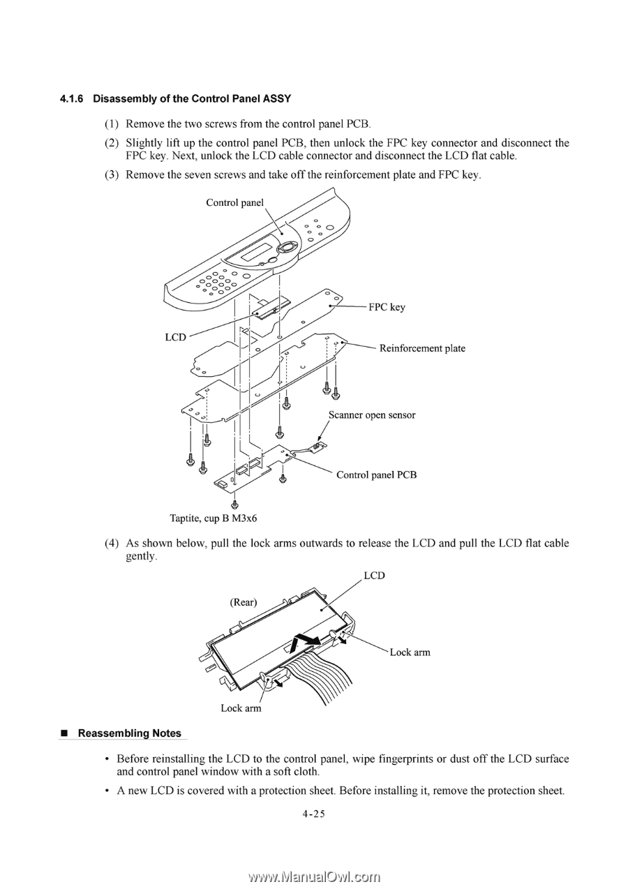
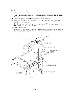
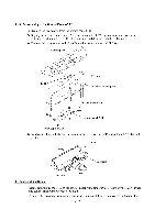
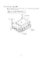
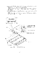
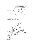
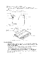
4.1.6 Disassembly of the Control Panel ASSY (1) Remove the two screws from the control panel PCB. (2) Slightly lift up the control panel PCB, then unlock the FPC key connector and disconnect the FPC key. Next, unlock the LCD cable connector and disconnect the LCD flat cable. (3) Remove the seven screws and take off the reinforcement plate and FPC key. Control panel O 0 0 0 070 c, o OHO LCD 0 O FPC key Reinforcement plate Scanner open sensor Control panel PCB 6 Taptite, cup B M3x6 (4) As shown below, pull the lock arms outwards to release the LCD and pull the LCD flat cable gently. LCD (Rear) Lock arm Lock arm • Reassembling Notes • Before reinstalling the LCD to the control panel, wipe fingerprints or dust off the LCD surface and control panel window with a soft cloth. • A new LCD is covered with a protection sheet. Before installing it, remove the protection sheet. 4 -2 5
-
 1
1 -
2
-
3
-
4
-
5
-
6
-
7
-
8
-
9
-
10
-
11
-
12
-
13
-
14
-
15
-
16
-
17
-
18
-
19
-
20
-
21
-
22
-
23
-
24
-
25
-
26
-
27
-
28
-
29
-
30
-
31
-
32
-
33
-
34
-
35
-
36
-
37
-
38
-
39
-
40
-
41
-
42
-
43
-
44
-
45
-
46
-
47
-
 48
48 -
 49
49 -
 50
50 -
 51
51 -
 52
52 -
 53
53 -
 54
54 -
 55
55 -
 56
56 -
 57
57 -
 58
58 -
59
-
60
-
61
-
62
-
63
-
64
-
65
-
66
-
67
-
68
-
69
-
70
-
71
-
72
-
73
-
74
-
75
-
76
-
77
-
78
-
79
-
80
-
81
-
82
-
83
-
84
-
85
-
86
-
87
-
88
-
89
-
90
-
91
-
92
-
93
-
94
-
95
-
96
-
97
-
98
-
99
-
100
-
101
-
102
-
103
-
104
-
105
-
106
-
107
-
108
-
109
-
110
-
111
-
112
-
113
-
114
-
115
-
116
-
117
-
118
-
119
-
120
-
121
-
122
-
123
-
124
-
125
-
126
-
127
-
128
-
129
-
130
-
131
-
132
-
133
-
134
-
135
-
136
-
137
-
138
-
139
-
140
-
141
-
142
-
143
-
144
-
145
-
146
-
147
-
148
-
149
-
150
-
151
-
152
-
153
-
154
-
155
-
156
-
157
-
158
-
159
-
160
-
161
-
162
-
163
-
164
-
165
-
166
-
167
-
168
-
169
-
170
-
171
-
172
-
173
-
174
-
175
-
176
-
177
-
178
-
179
-
180
-
181
-
182
-
183
-
184
-
185
-
186
-
187
-
188
-
189
-
190
-
191
-
192
-
193
-
194
-
195
-
196
-
197
-
198
-
199
-
200
-
201
-
202
-
203
-
204
 |
 |