Brother International DCP1000 Service Manual - Page 104
double-digit
 |
UPC - 012502565796
View all Brother International DCP1000 manuals
Add to My Manuals
Save this manual to your list of manuals |
Page 104 highlights
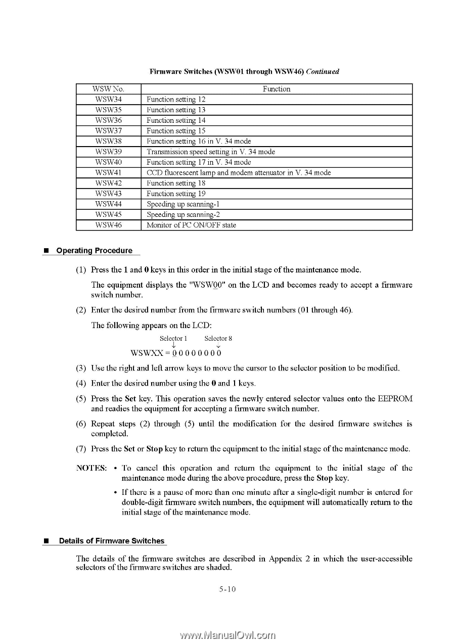
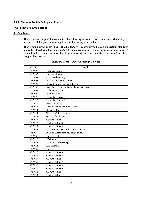
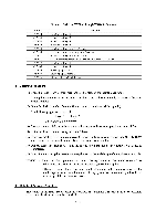
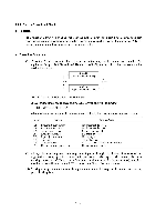
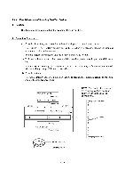
WSW No. WSW34 WSW35 WSW36 WSW37 WSW38 WSW39 WSW40 WSW41 WSW42 WSW43 WSW44 WSW45 WSW46 Firmware Switches (WSW01 through WSW46) Continued Function Function setting 12 Function setting 13 Function setting 14 Function setting 15 Function setting 16 in V. 34 mode Transmission speed setting in V. 34 mode Function setting 17 in V. 34 mode CCD fluorescent lamp and modem attenuator in V. 34 mode Function setting 18 Function setting 19 Speeding up scanning-1 Speeding up scanning-2 Monitor of PC ON/OFF state • Operating Procedure (1) Press the 1 and 0 keys in this order in the initial stage of the maintenance mode. The equipment displays the "WSWOO" on the LCD and becomes ready to accept a firmware switch number. (2) Enter the desired number from the firmware switch numbers (01 through 46). The following appears on the LCD: Selector 1 Selector 8 WSWXX = 0 0 0 0 0 0 0 0 (3) Use the right and left arrow keys to move the cursor to the selector position to be modified. (4) Enter the desired number using the 0 and 1 keys. (5) Press the Set key. This operation saves the newly entered selector values onto the EEPROM and readies the equipment for accepting a firmware switch number. (6) Repeat steps (2) through (5) until the modification for the desired firmware switches is completed. (7) Press the Set or Stop key to return the equipment to the initial stage of the maintenance mode. NOTES: • To cancel this operation and return the equipment to the initial stage of the maintenance mode during the above procedure, press the Stop key. • If there is a pause of more than one minute after a single-digit number is entered for double-digit firmware switch numbers, the equipment will automatically return to the initial stage of the maintenance mode. • Details of Firmware Switches The details of the firmware switches are described in Appendix 2 in which the user-accessible selectors of the firmware switches are shaded. 5-10
-
 1
1 -
2
-
3
-
4
-
5
-
6
-
7
-
8
-
9
-
10
-
11
-
12
-
13
-
14
-
15
-
16
-
17
-
18
-
19
-
20
-
21
-
22
-
23
-
24
-
25
-
26
-
27
-
28
-
29
-
30
-
31
-
32
-
33
-
34
-
35
-
36
-
37
-
38
-
39
-
40
-
41
-
42
-
43
-
44
-
45
-
46
-
47
-
48
-
49
-
50
-
51
-
52
-
53
-
54
-
55
-
56
-
57
-
58
-
59
-
60
-
61
-
62
-
63
-
64
-
65
-
66
-
67
-
68
-
69
-
70
-
71
-
72
-
73
-
74
-
75
-
76
-
77
-
78
-
79
-
80
-
81
-
82
-
83
-
84
-
85
-
86
-
87
-
88
-
89
-
90
-
91
-
92
-
93
-
94
-
95
-
96
-
97
-
98
-
 99
99 -
 100
100 -
 101
101 -
 102
102 -
 103
103 -
 104
104 -
 105
105 -
 106
106 -
 107
107 -
 108
108 -
 109
109 -
110
-
111
-
112
-
113
-
114
-
115
-
116
-
117
-
118
-
119
-
120
-
121
-
122
-
123
-
124
-
125
-
126
-
127
-
128
-
129
-
130
-
131
-
132
-
133
-
134
-
135
-
136
-
137
-
138
-
139
-
140
-
141
-
142
-
143
-
144
-
145
-
146
-
147
-
148
-
149
-
150
-
151
-
152
-
153
-
154
-
155
-
156
-
157
-
158
-
159
-
160
-
161
-
162
-
163
-
164
-
165
-
166
-
167
-
168
-
169
-
170
-
171
-
172
-
173
-
174
-
175
-
176
-
177
-
178
-
179
-
180
-
181
-
182
-
183
-
184
-
185
-
186
-
187
-
188
-
189
-
190
-
191
-
192
-
193
-
194
-
195
-
196
-
197
-
198
-
199
-
200
-
201
-
202
-
203
-
204
 |
 |