Brother International DCP1000 Service Manual - Page 99
background
 |
UPC - 012502565796
View all Brother International DCP1000 manuals
Add to My Manuals
Save this manual to your list of manuals |
Page 99 highlights
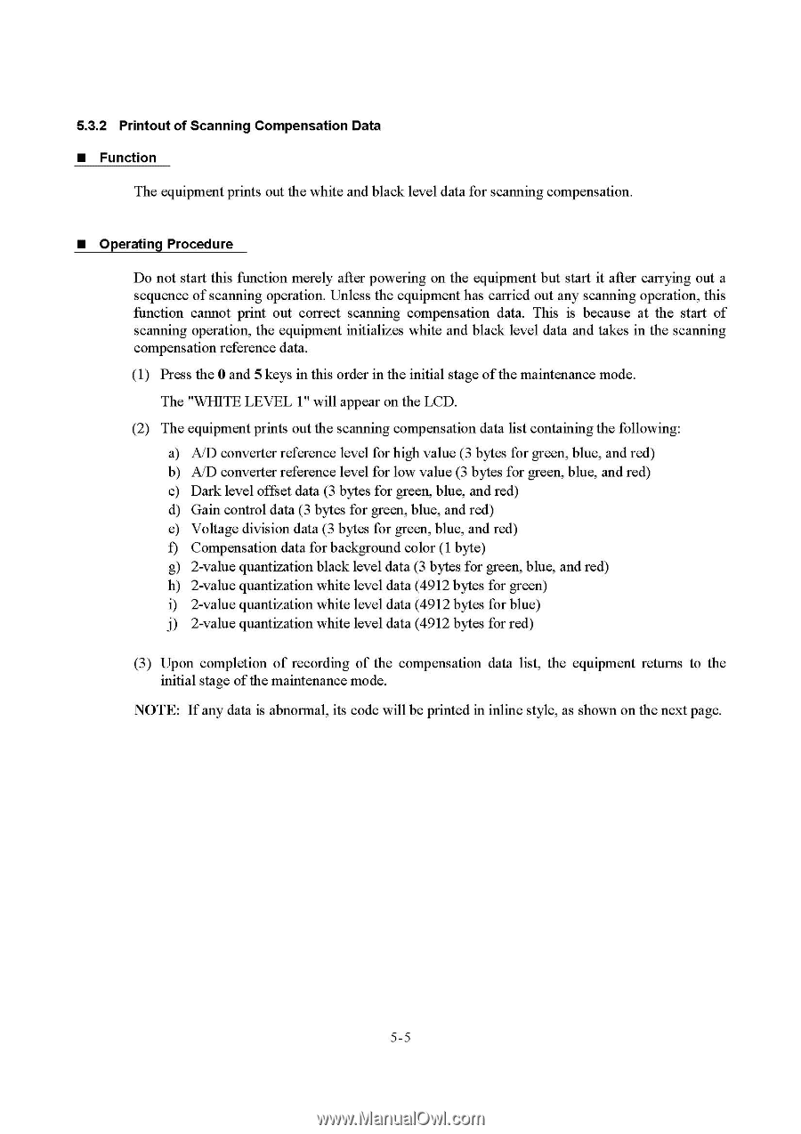
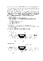
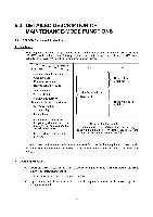
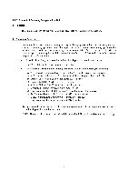
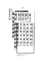
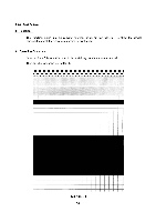
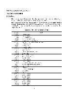
5.3.2 Printout of Scanning Compensation Data ■ Function The equipment prints out the white and black level data for scanning compensation. ■ Operating Procedure Do not start this function merely after powering on the equipment but start it after carrying out a sequence of scanning operation. Unless the equipment has carried out any scanning operation, this function cannot print out correct scanning compensation data. This is because at the start of scanning operation, the equipment initializes white and black level data and takes in the scanning compensation reference data. (1) Press the 0 and 5 keys in this order in the initial stage of the maintenance mode. The "WHITE LEVEL 1" will appear on the LCD. (2) The equipment prints out the scanning compensation data list containing the following: a) AID converter reference level for high value (3 bytes for green, blue, and red) b) AID converter reference level for low value (3 bytes for green, blue, and red) c) Dark level offset data (3 bytes for green, blue, and red) d) Gain control data (3 bytes for green, blue, and red) e) Voltage division data (3 bytes for green, blue, and red) f) Compensation data for background color (1 byte) g) 2-value quantization black level data (3 bytes for green, blue, and red) h) 2-value quantization white level data (4912 bytes for green) i) 2-value quantization white level data (4912 bytes for blue) j) 2-value quantization white level data (4912 bytes for red) (3) Upon completion of recording of the compensation data list, the equipment returns to the initial stage of the maintenance mode. NOTE: If any data is abnormal, its code will be printed in inline style, as shown on the next page. 5-5
-
 1
1 -
2
-
3
-
4
-
5
-
6
-
7
-
8
-
9
-
10
-
11
-
12
-
13
-
14
-
15
-
16
-
17
-
18
-
19
-
20
-
21
-
22
-
23
-
24
-
25
-
26
-
27
-
28
-
29
-
30
-
31
-
32
-
33
-
34
-
35
-
36
-
37
-
38
-
39
-
40
-
41
-
42
-
43
-
44
-
45
-
46
-
47
-
48
-
49
-
50
-
51
-
52
-
53
-
54
-
55
-
56
-
57
-
58
-
59
-
60
-
61
-
62
-
63
-
64
-
65
-
66
-
67
-
68
-
69
-
70
-
71
-
72
-
73
-
74
-
75
-
76
-
77
-
78
-
79
-
80
-
81
-
82
-
83
-
84
-
85
-
86
-
87
-
88
-
89
-
90
-
91
-
92
-
93
-
 94
94 -
 95
95 -
 96
96 -
 97
97 -
 98
98 -
 99
99 -
 100
100 -
 101
101 -
 102
102 -
 103
103 -
 104
104 -
105
-
106
-
107
-
108
-
109
-
110
-
111
-
112
-
113
-
114
-
115
-
116
-
117
-
118
-
119
-
120
-
121
-
122
-
123
-
124
-
125
-
126
-
127
-
128
-
129
-
130
-
131
-
132
-
133
-
134
-
135
-
136
-
137
-
138
-
139
-
140
-
141
-
142
-
143
-
144
-
145
-
146
-
147
-
148
-
149
-
150
-
151
-
152
-
153
-
154
-
155
-
156
-
157
-
158
-
159
-
160
-
161
-
162
-
163
-
164
-
165
-
166
-
167
-
168
-
169
-
170
-
171
-
172
-
173
-
174
-
175
-
176
-
177
-
178
-
179
-
180
-
181
-
182
-
183
-
184
-
185
-
186
-
187
-
188
-
189
-
190
-
191
-
192
-
193
-
194
-
195
-
196
-
197
-
198
-
199
-
200
-
201
-
202
-
203
-
204
 |
 |