Brother International DCP1000 Service Manual - Page 27
Disassembly/reassembly, Lubrication, Contents
 |
UPC - 012502565796
View all Brother International DCP1000 manuals
Add to My Manuals
Save this manual to your list of manuals |
Page 27 highlights
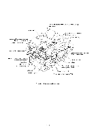
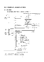
CHAPTER 4 DISASSEMBLY/REASSEMBLY AND LUBRICATION CONTENTS 4.1 DISASSEMBLY/REASSEMBLY ■ Safety Precautions Tightening Torque List ■ Preparation ■ How to Access the Object Component ■ Disassembly Order Flow 4.1.1 ADF Cover and Document Guide Base 4.1.2 ADF Components on the Upper ADF Chute 4.1.3 ADF Components on the Lower ADF Chute 4.1.4 Document Tray Open Sensor and Document Stopper 4.1.5 Scanner Unit and Control Panel ASSY (Together with Document Tray) 4.1.6 Disassembly of the Control Panel ASSY 4.1.7 Disassembly of the Scanner Unit 4.1.8 Front Cover 4.1.9 Relay PCB 4.1.10 Scanner Mount 4.1.11 Board Access Cover and Auto Sheet Feeder (ASF) 4.1.12 Heat-fixing Unit, FU Lamp, and Paper Ejection Sensor Actuator 4.1.13 Laser Unit and Toner Sensor PCB 4.1.14 Main PCB 4.1.15 Bottom Plate 4.1.16 Low-voltage Power Supply PCB 4.1.17 High-voltage Power Supply PCB 4.1.18 Main-Fan PCB, Duct, and Fan 4.1.19 Power Supply Shield 4.1.20 Speaker 4.1.21 Gear Drive Unit 4-1 4-1 4-2 4-4 4-4 4-5 4-6 4-7 4-12 4-17 4-18 4-25 4-26 4-31 4-32 4-33 4-34 4-40 4-42 4-43 4-46 4-47 4-48 4-49 4-50 4-51 4-52
-
 1
1 -
2
-
3
-
4
-
5
-
6
-
7
-
8
-
9
-
10
-
11
-
12
-
13
-
14
-
15
-
16
-
17
-
18
-
19
-
20
-
21
-
 22
22 -
 23
23 -
 24
24 -
 25
25 -
 26
26 -
 27
27 -
 28
28 -
 29
29 -
 30
30 -
 31
31 -
 32
32 -
33
-
34
-
35
-
36
-
37
-
38
-
39
-
40
-
41
-
42
-
43
-
44
-
45
-
46
-
47
-
48
-
49
-
50
-
51
-
52
-
53
-
54
-
55
-
56
-
57
-
58
-
59
-
60
-
61
-
62
-
63
-
64
-
65
-
66
-
67
-
68
-
69
-
70
-
71
-
72
-
73
-
74
-
75
-
76
-
77
-
78
-
79
-
80
-
81
-
82
-
83
-
84
-
85
-
86
-
87
-
88
-
89
-
90
-
91
-
92
-
93
-
94
-
95
-
96
-
97
-
98
-
99
-
100
-
101
-
102
-
103
-
104
-
105
-
106
-
107
-
108
-
109
-
110
-
111
-
112
-
113
-
114
-
115
-
116
-
117
-
118
-
119
-
120
-
121
-
122
-
123
-
124
-
125
-
126
-
127
-
128
-
129
-
130
-
131
-
132
-
133
-
134
-
135
-
136
-
137
-
138
-
139
-
140
-
141
-
142
-
143
-
144
-
145
-
146
-
147
-
148
-
149
-
150
-
151
-
152
-
153
-
154
-
155
-
156
-
157
-
158
-
159
-
160
-
161
-
162
-
163
-
164
-
165
-
166
-
167
-
168
-
169
-
170
-
171
-
172
-
173
-
174
-
175
-
176
-
177
-
178
-
179
-
180
-
181
-
182
-
183
-
184
-
185
-
186
-
187
-
188
-
189
-
190
-
191
-
192
-
193
-
194
-
195
-
196
-
197
-
198
-
199
-
200
-
201
-
202
-
203
-
204
 |
 |