Brother International DCP1000 Service Manual - Page 51
disconnect
 |
UPC - 012502565796
View all Brother International DCP1000 manuals
Add to My Manuals
Save this manual to your list of manuals |
Page 51 highlights
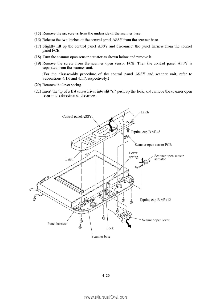
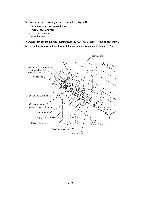
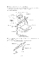
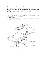
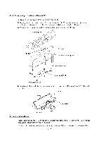
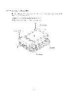
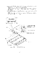
(15) Remove the six screws from the underside of the scanner base. (16) Release the two latches of the control panel ASSY from the scanner base. (17) Slightly lift up the control panel ASSY and disconnect the panel harness from the control panel PCB. (18) Turn the scanner open sensor actuator as shown below and remove it. (19) Remove the screw from the scanner open sensor PCB. Then the control panel ASSY is separated from the scanner unit. (For the disassembly procedure of the control panel ASSY and scanner unit, refer to Subsections 4.1.6 and 4.1.7, respectively.) (20) Remove the lever spring. (21) Insert the tip of a flat screwdriver into slit "s," push up the lock, and remove the scanner open lever in the direction of the arrow. Control panel ASSY O C> 0 0 0 CD . 00 . 0 0 0 C2> . Latch Latch o o 0 Taptite, cup B M3x8 it Scanner open sensor PCB Lever spring Scanner open sensor actuator Panel harness Lock Scanner base Taptite, cup B M3x12 Scanner open lever 4-23
-
 1
1 -
2
-
3
-
4
-
5
-
6
-
7
-
8
-
9
-
10
-
11
-
12
-
13
-
14
-
15
-
16
-
17
-
18
-
19
-
20
-
21
-
22
-
23
-
24
-
25
-
26
-
27
-
28
-
29
-
30
-
31
-
32
-
33
-
34
-
35
-
36
-
37
-
38
-
39
-
40
-
41
-
42
-
43
-
44
-
45
-
 46
46 -
 47
47 -
 48
48 -
 49
49 -
 50
50 -
 51
51 -
 52
52 -
 53
53 -
 54
54 -
 55
55 -
 56
56 -
57
-
58
-
59
-
60
-
61
-
62
-
63
-
64
-
65
-
66
-
67
-
68
-
69
-
70
-
71
-
72
-
73
-
74
-
75
-
76
-
77
-
78
-
79
-
80
-
81
-
82
-
83
-
84
-
85
-
86
-
87
-
88
-
89
-
90
-
91
-
92
-
93
-
94
-
95
-
96
-
97
-
98
-
99
-
100
-
101
-
102
-
103
-
104
-
105
-
106
-
107
-
108
-
109
-
110
-
111
-
112
-
113
-
114
-
115
-
116
-
117
-
118
-
119
-
120
-
121
-
122
-
123
-
124
-
125
-
126
-
127
-
128
-
129
-
130
-
131
-
132
-
133
-
134
-
135
-
136
-
137
-
138
-
139
-
140
-
141
-
142
-
143
-
144
-
145
-
146
-
147
-
148
-
149
-
150
-
151
-
152
-
153
-
154
-
155
-
156
-
157
-
158
-
159
-
160
-
161
-
162
-
163
-
164
-
165
-
166
-
167
-
168
-
169
-
170
-
171
-
172
-
173
-
174
-
175
-
176
-
177
-
178
-
179
-
180
-
181
-
182
-
183
-
184
-
185
-
186
-
187
-
188
-
189
-
190
-
191
-
192
-
193
-
194
-
195
-
196
-
197
-
198
-
199
-
200
-
201
-
202
-
203
-
204
 |
 |