Brother International DCP1000 Service Manual - Page 52
cable clip
 |
UPC - 012502565796
View all Brother International DCP1000 manuals
Add to My Manuals
Save this manual to your list of manuals |
Page 52 highlights
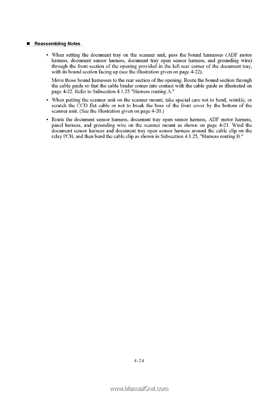
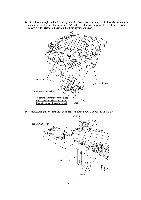
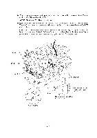
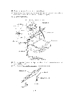
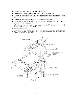
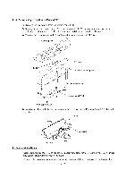
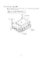
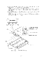
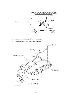
■ Reassembling Notes • When setting the document tray on the scanner unit, pass the bound harnesses (ADF motor harness, document sensor harness, document tray open sensor harness, and grounding wire) through the front section of the opening provided in the left rear corner of the document tray, with its bound section facing up (see the illustration given on page 4-22). Move those bound harnesses to the rear section of the opening. Route the bound section through the cable guide so that the cable binder comes into contact with the cable guide as illustrated on page 4-22. Refer to Subsection 4.1.25 "Harness routing A." • When putting the scanner unit on the scanner mount, take special care not to bend, wrinkle, or scratch the CCD flat cable or not to break the boss of the front cover by the bottom of the scanner unit. (See the illustration given on page 4-20.) • Route the document sensor harness, document tray open sensor harness, ADF motor harness, panel harness, and grounding wire on the scanner mount as shown on page 4-21. Wind the document sensor harness and document tray open sensor harness around the cable clip on the relay PCB, and then bend the cable clip as shown in Subsection 4.1.25, "Harness routing B." 4 -24
-
 1
1 -
2
-
3
-
4
-
5
-
6
-
7
-
8
-
9
-
10
-
11
-
12
-
13
-
14
-
15
-
16
-
17
-
18
-
19
-
20
-
21
-
22
-
23
-
24
-
25
-
26
-
27
-
28
-
29
-
30
-
31
-
32
-
33
-
34
-
35
-
36
-
37
-
38
-
39
-
40
-
41
-
42
-
43
-
44
-
45
-
46
-
 47
47 -
 48
48 -
 49
49 -
 50
50 -
 51
51 -
 52
52 -
 53
53 -
 54
54 -
 55
55 -
 56
56 -
 57
57 -
58
-
59
-
60
-
61
-
62
-
63
-
64
-
65
-
66
-
67
-
68
-
69
-
70
-
71
-
72
-
73
-
74
-
75
-
76
-
77
-
78
-
79
-
80
-
81
-
82
-
83
-
84
-
85
-
86
-
87
-
88
-
89
-
90
-
91
-
92
-
93
-
94
-
95
-
96
-
97
-
98
-
99
-
100
-
101
-
102
-
103
-
104
-
105
-
106
-
107
-
108
-
109
-
110
-
111
-
112
-
113
-
114
-
115
-
116
-
117
-
118
-
119
-
120
-
121
-
122
-
123
-
124
-
125
-
126
-
127
-
128
-
129
-
130
-
131
-
132
-
133
-
134
-
135
-
136
-
137
-
138
-
139
-
140
-
141
-
142
-
143
-
144
-
145
-
146
-
147
-
148
-
149
-
150
-
151
-
152
-
153
-
154
-
155
-
156
-
157
-
158
-
159
-
160
-
161
-
162
-
163
-
164
-
165
-
166
-
167
-
168
-
169
-
170
-
171
-
172
-
173
-
174
-
175
-
176
-
177
-
178
-
179
-
180
-
181
-
182
-
183
-
184
-
185
-
186
-
187
-
188
-
189
-
190
-
191
-
192
-
193
-
194
-
195
-
196
-
197
-
198
-
199
-
200
-
201
-
202
-
203
-
204
 |
 |