Brother International DCP1000 Service Manual - Page 44
drive, Taptite, Screw, washer, motor, Lower, chute
 |
UPC - 012502565796
View all Brother International DCP1000 manuals
Add to My Manuals
Save this manual to your list of manuals |
Page 44 highlights
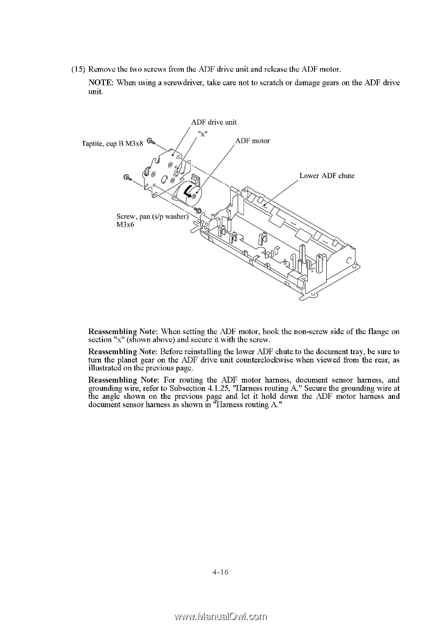
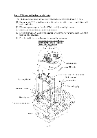
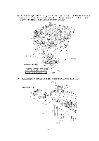
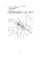
(15) Remove the two screws from the ADF drive unit and release the ADF motor. NOTE: When using a screwdriver, take care not to scratch or damage gears on the ADF drive unit. Taptite, cup B M3x8 ADF drive unit flx n ADF motor 0 0 C' Lower ADF chute Screw, pan (s/p washer M3x6 C Reassembling Note: When setting the ADF motor, hook the non-screw side of the flange on section "x" (shown above) and secure it with the screw. Reassembling Note: Before reinstalling the lower ADF chute to the document tray, be sure to turn the planet gear on the ADF drive unit counterclockwise when viewed from the rear, as illustrated on the previous page. Reassembling Note: For routing the ADF motor harness, document sensor harness, and grounding wire, refer to Subsection 4.1.25, "Harness routing A." Secure the grounding wire at the angle shown on the previous page and let it hold down the ADF motor harness and document sensor harness as shown in "Harness routing A." 4-16
-
 1
1 -
2
-
3
-
4
-
5
-
6
-
7
-
8
-
9
-
10
-
11
-
12
-
13
-
14
-
15
-
16
-
17
-
18
-
19
-
20
-
21
-
22
-
23
-
24
-
25
-
26
-
27
-
28
-
29
-
30
-
31
-
32
-
33
-
34
-
35
-
36
-
37
-
38
-
 39
39 -
 40
40 -
 41
41 -
 42
42 -
 43
43 -
 44
44 -
 45
45 -
 46
46 -
 47
47 -
 48
48 -
 49
49 -
50
-
51
-
52
-
53
-
54
-
55
-
56
-
57
-
58
-
59
-
60
-
61
-
62
-
63
-
64
-
65
-
66
-
67
-
68
-
69
-
70
-
71
-
72
-
73
-
74
-
75
-
76
-
77
-
78
-
79
-
80
-
81
-
82
-
83
-
84
-
85
-
86
-
87
-
88
-
89
-
90
-
91
-
92
-
93
-
94
-
95
-
96
-
97
-
98
-
99
-
100
-
101
-
102
-
103
-
104
-
105
-
106
-
107
-
108
-
109
-
110
-
111
-
112
-
113
-
114
-
115
-
116
-
117
-
118
-
119
-
120
-
121
-
122
-
123
-
124
-
125
-
126
-
127
-
128
-
129
-
130
-
131
-
132
-
133
-
134
-
135
-
136
-
137
-
138
-
139
-
140
-
141
-
142
-
143
-
144
-
145
-
146
-
147
-
148
-
149
-
150
-
151
-
152
-
153
-
154
-
155
-
156
-
157
-
158
-
159
-
160
-
161
-
162
-
163
-
164
-
165
-
166
-
167
-
168
-
169
-
170
-
171
-
172
-
173
-
174
-
175
-
176
-
177
-
178
-
179
-
180
-
181
-
182
-
183
-
184
-
185
-
186
-
187
-
188
-
189
-
190
-
191
-
192
-
193
-
194
-
195
-
196
-
197
-
198
-
199
-
200
-
201
-
202
-
203
-
204
 |
 |