Brother International DCP1000 Service Manual - Page 69
Upper, cover, Taptite, M3x12, M3x10, plate, Heater, roller, Lower, Screw, washer, M2.6x6DA
 |
UPC - 012502565796
View all Brother International DCP1000 manuals
Add to My Manuals
Save this manual to your list of manuals |
Page 69 highlights
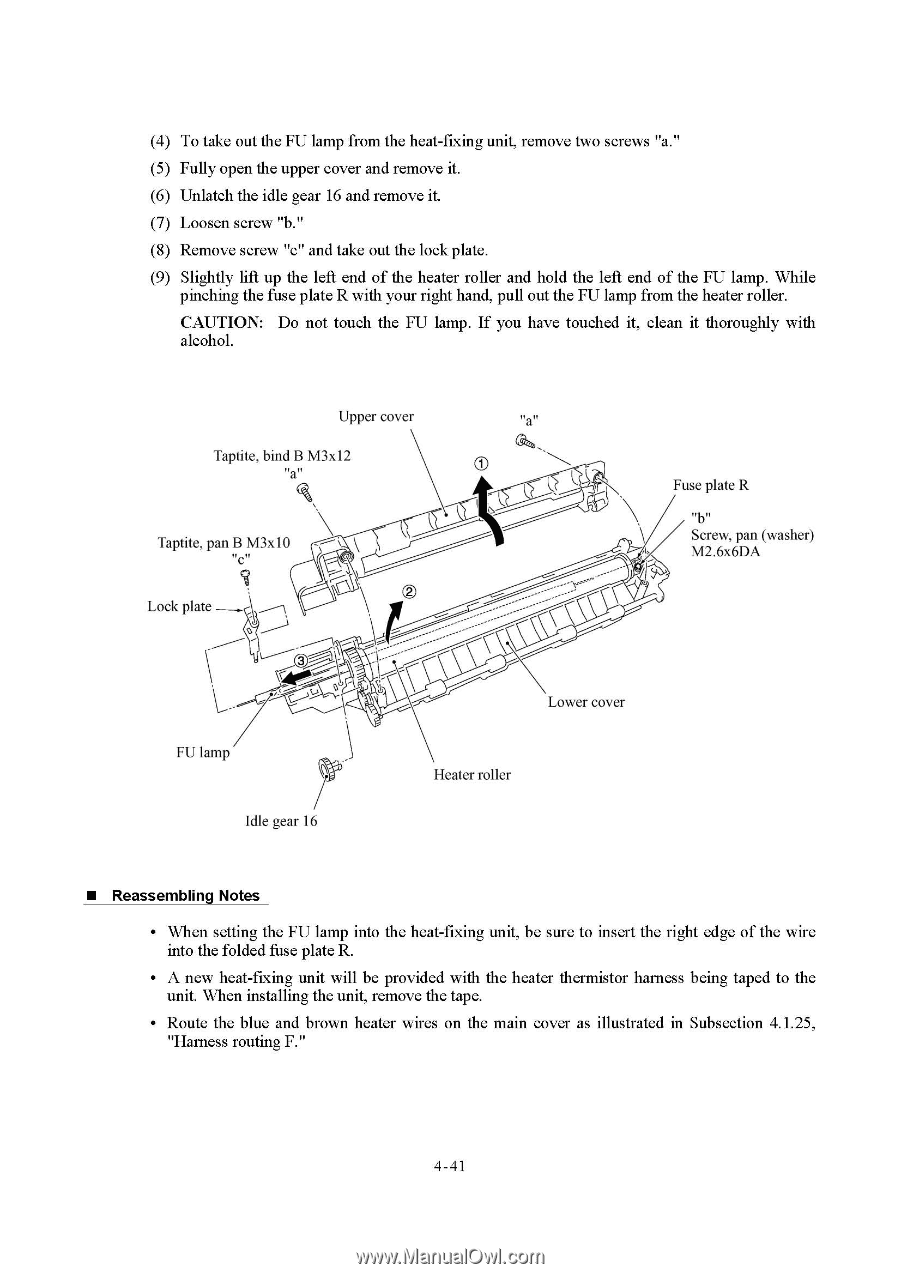
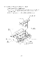
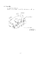
(4) To take out the FU lamp from the heat-fixing unit, remove two screws "a." (5) Fully open the upper cover and remove it. (6) Unlatch the idle gear 16 and remove it. (7) Loosen screw "b." (8) Remove screw "c" and take out the lock plate. (9) Slightly lift up the left end of the heater roller and hold the left end of the FU lamp. While pinching the fuse plate R with your right hand, pull out the FU lamp from the heater roller. CAUTION: Do not touch the FU lamp. If you have touched it, clean it thoroughly with alcohol. Upper cover "a" Taptite, bind B M3x12 "a" Taptite, pan B M3x10 "c" 7 Lock plate Fuse plate R "b" Screw, pan (washer) M2.6x6DA FU lamp Idle gear 16 Lower cover Heater roller • Reassembling Notes • When setting the FU lamp into the heat-fixing unit, be sure to insert the right edge of the wire into the folded fuse plate R. • A new heat-fixing unit will be provided with the heater thermistor harness being taped to the unit. When installing the unit, remove the tape. • Route the blue and brown heater wires on the main cover as illustrated in Subsection 4.1.25, "Harness routing F." 4-41
-
 1
1 -
2
-
3
-
4
-
5
-
6
-
7
-
8
-
9
-
10
-
11
-
12
-
13
-
14
-
15
-
16
-
17
-
18
-
19
-
20
-
21
-
22
-
23
-
24
-
25
-
26
-
27
-
28
-
29
-
30
-
31
-
32
-
33
-
34
-
35
-
36
-
37
-
38
-
39
-
40
-
41
-
42
-
43
-
44
-
45
-
46
-
47
-
48
-
49
-
50
-
51
-
52
-
53
-
54
-
55
-
56
-
57
-
58
-
59
-
60
-
61
-
62
-
63
-
 64
64 -
 65
65 -
 66
66 -
 67
67 -
 68
68 -
 69
69 -
 70
70 -
 71
71 -
 72
72 -
 73
73 -
 74
74 -
75
-
76
-
77
-
78
-
79
-
80
-
81
-
82
-
83
-
84
-
85
-
86
-
87
-
88
-
89
-
90
-
91
-
92
-
93
-
94
-
95
-
96
-
97
-
98
-
99
-
100
-
101
-
102
-
103
-
104
-
105
-
106
-
107
-
108
-
109
-
110
-
111
-
112
-
113
-
114
-
115
-
116
-
117
-
118
-
119
-
120
-
121
-
122
-
123
-
124
-
125
-
126
-
127
-
128
-
129
-
130
-
131
-
132
-
133
-
134
-
135
-
136
-
137
-
138
-
139
-
140
-
141
-
142
-
143
-
144
-
145
-
146
-
147
-
148
-
149
-
150
-
151
-
152
-
153
-
154
-
155
-
156
-
157
-
158
-
159
-
160
-
161
-
162
-
163
-
164
-
165
-
166
-
167
-
168
-
169
-
170
-
171
-
172
-
173
-
174
-
175
-
176
-
177
-
178
-
179
-
180
-
181
-
182
-
183
-
184
-
185
-
186
-
187
-
188
-
189
-
190
-
191
-
192
-
193
-
194
-
195
-
196
-
197
-
198
-
199
-
200
-
201
-
202
-
203
-
204
 |
 |