Brother International DCP1000 Service Manual - Page 109
correction
 |
UPC - 012502565796
View all Brother International DCP1000 manuals
Add to My Manuals
Save this manual to your list of manuals |
Page 109 highlights
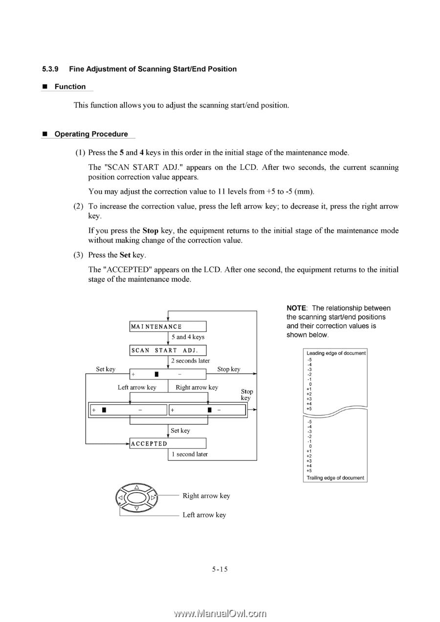
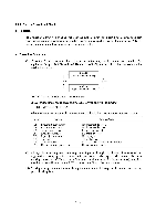
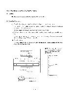
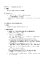
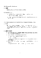
5.3.9 Fine Adjustment of Scanning Start/End Position ■ Function This function allows you to adjust the scanning start/end position. ■ Operating Procedure (1) Press the 5 and 4 keys in this order in the initial stage of the maintenance mode. The "SCAN START ADJ." appears on the LCD. After two seconds, the current scanning position correction value appears. You may adjust the correction value to I I levels from +5 to -5 (mm). (2) To increase the correction value, press the left arrow key; to decrease it, press the right arrow key. If you press the Stop key, the equipment returns to the initial stage of the maintenance mode without making change of the correction value. (3) Press the Set key. The "ACCEPTED" appears on the LCD. After one second, the equipment returns to the initial stage of the maintenance mode. Set key MAINTENANCE 5 and 4 keys SCAN START ADJ. 2 seconds later Stop key Left arrow key Right arrow key Stop key Set key 0-ACCEPTED I second later Right arrow key v Left arrow key NOTE: The relationship between the scanning start/end positions and their correction values is shown below. Leading edge of document -5 -4 -3 -2 0 +1 +2 +3 +4 +5 -5 -4 -3 -2 0 +1 +2 +3 +4 +5 Trailing edge of document 5-1 5
-
 1
1 -
2
-
3
-
4
-
5
-
6
-
7
-
8
-
9
-
10
-
11
-
12
-
13
-
14
-
15
-
16
-
17
-
18
-
19
-
20
-
21
-
22
-
23
-
24
-
25
-
26
-
27
-
28
-
29
-
30
-
31
-
32
-
33
-
34
-
35
-
36
-
37
-
38
-
39
-
40
-
41
-
42
-
43
-
44
-
45
-
46
-
47
-
48
-
49
-
50
-
51
-
52
-
53
-
54
-
55
-
56
-
57
-
58
-
59
-
60
-
61
-
62
-
63
-
64
-
65
-
66
-
67
-
68
-
69
-
70
-
71
-
72
-
73
-
74
-
75
-
76
-
77
-
78
-
79
-
80
-
81
-
82
-
83
-
84
-
85
-
86
-
87
-
88
-
89
-
90
-
91
-
92
-
93
-
94
-
95
-
96
-
97
-
98
-
99
-
100
-
101
-
102
-
103
-
 104
104 -
 105
105 -
 106
106 -
 107
107 -
 108
108 -
 109
109 -
 110
110 -
 111
111 -
 112
112 -
 113
113 -
 114
114 -
115
-
116
-
117
-
118
-
119
-
120
-
121
-
122
-
123
-
124
-
125
-
126
-
127
-
128
-
129
-
130
-
131
-
132
-
133
-
134
-
135
-
136
-
137
-
138
-
139
-
140
-
141
-
142
-
143
-
144
-
145
-
146
-
147
-
148
-
149
-
150
-
151
-
152
-
153
-
154
-
155
-
156
-
157
-
158
-
159
-
160
-
161
-
162
-
163
-
164
-
165
-
166
-
167
-
168
-
169
-
170
-
171
-
172
-
173
-
174
-
175
-
176
-
177
-
178
-
179
-
180
-
181
-
182
-
183
-
184
-
185
-
186
-
187
-
188
-
189
-
190
-
191
-
192
-
193
-
194
-
195
-
196
-
197
-
198
-
199
-
200
-
201
-
202
-
203
-
204
 |
 |