Brother International DCP1000 Service Manual - Page 71
Ccd/panel
 |
UPC - 012502565796
View all Brother International DCP1000 manuals
Add to My Manuals
Save this manual to your list of manuals |
Page 71 highlights
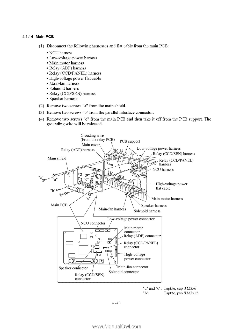
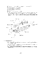
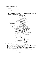
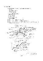
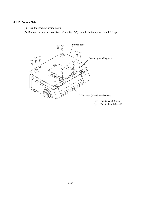
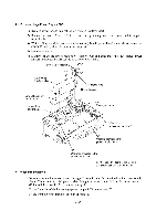
4.1.14 Main PCB (1) Disconnect the following harnesses and flat cable from the main PCB: • NCU harness • Lowvoltage power harness • Main motor harness • Relay (ADF) harness • Relay (CCD/PANEL) harness • Highvoltage power flat cable • Main-fan harness • Solenoid harness • Relay (CCD/SEN) harness • Speaker harness (2) Remove two screws "a" from the main shield. (3) Remove two screws "b" from the parallel interface connector. (4) Remove two screws "c" from the main PCB and then take it off from the PCB support. The grounding wire will be released. Grouding wire (From the relay PCB) Main cover Relay (ADF) harness Main shield PCB support Low-voltage power harness Relay (CCD/SEN) harness Relay (CCD/PANEL) harness NCU harness a,, 00.-- "a" "c" "b" COm"b" "c" I III]] High-voltage power flat cable 1 1 Main motor harness Main PCB Main-fan harness Speaker harness Solenoid harness Low-voltage power connector NCU connector mm-71. Main motor connector Relay (ADF) connector 0 ) 0 El= ft Relay (CCD/PANEL) connector High-voltage power connector Speaker connector Relay (CCD/SEN) connector 'Main-fan connector Solenoid connector "a" and "c": Taptite, cup S M3x6 mu: Taptite, pan S M3x12 4-43
-
 1
1 -
2
-
3
-
4
-
5
-
6
-
7
-
8
-
9
-
10
-
11
-
12
-
13
-
14
-
15
-
16
-
17
-
18
-
19
-
20
-
21
-
22
-
23
-
24
-
25
-
26
-
27
-
28
-
29
-
30
-
31
-
32
-
33
-
34
-
35
-
36
-
37
-
38
-
39
-
40
-
41
-
42
-
43
-
44
-
45
-
46
-
47
-
48
-
49
-
50
-
51
-
52
-
53
-
54
-
55
-
56
-
57
-
58
-
59
-
60
-
61
-
62
-
63
-
64
-
65
-
 66
66 -
 67
67 -
 68
68 -
 69
69 -
 70
70 -
 71
71 -
 72
72 -
 73
73 -
 74
74 -
 75
75 -
 76
76 -
77
-
78
-
79
-
80
-
81
-
82
-
83
-
84
-
85
-
86
-
87
-
88
-
89
-
90
-
91
-
92
-
93
-
94
-
95
-
96
-
97
-
98
-
99
-
100
-
101
-
102
-
103
-
104
-
105
-
106
-
107
-
108
-
109
-
110
-
111
-
112
-
113
-
114
-
115
-
116
-
117
-
118
-
119
-
120
-
121
-
122
-
123
-
124
-
125
-
126
-
127
-
128
-
129
-
130
-
131
-
132
-
133
-
134
-
135
-
136
-
137
-
138
-
139
-
140
-
141
-
142
-
143
-
144
-
145
-
146
-
147
-
148
-
149
-
150
-
151
-
152
-
153
-
154
-
155
-
156
-
157
-
158
-
159
-
160
-
161
-
162
-
163
-
164
-
165
-
166
-
167
-
168
-
169
-
170
-
171
-
172
-
173
-
174
-
175
-
176
-
177
-
178
-
179
-
180
-
181
-
182
-
183
-
184
-
185
-
186
-
187
-
188
-
189
-
190
-
191
-
192
-
193
-
194
-
195
-
196
-
197
-
198
-
199
-
200
-
201
-
202
-
203
-
204
 |
 |