Brother International DCP1000 Service Manual - Page 47
right, edges, front, cover, cover, connector, direction, arrow, press, inwards, arrow, release,
 |
UPC - 012502565796
View all Brother International DCP1000 manuals
Add to My Manuals
Save this manual to your list of manuals |
Page 47 highlights
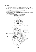
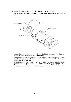
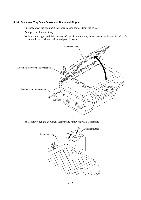
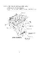
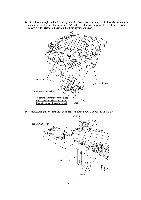
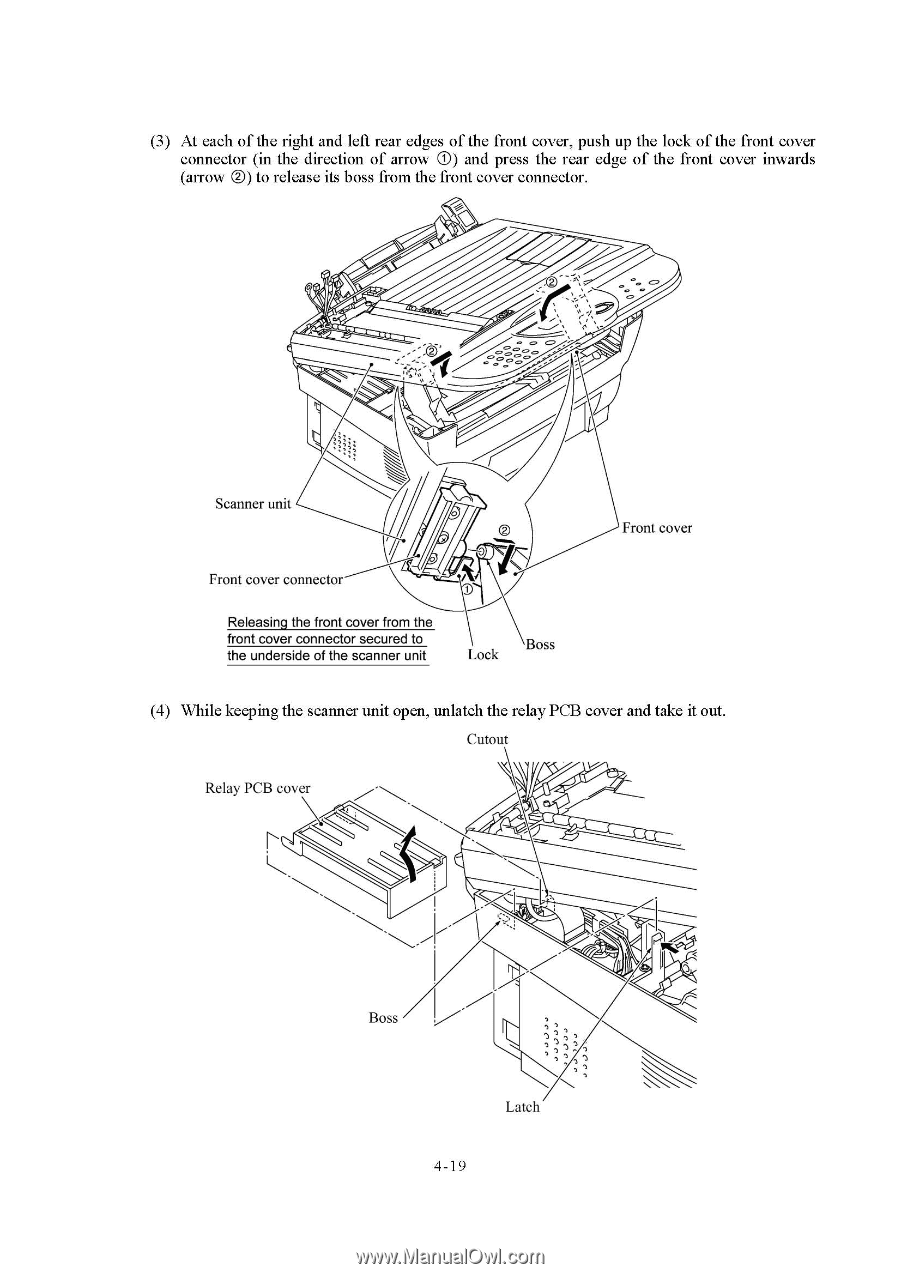
(3) At each of the right and left rear edges of the front cover, push up the lock of the front cover connector (in the direction of arrow 0) and press the rear edge of the front cover inwards (arrow 0) to release its boss from the front cover connector. 0 Scanner unit Front cover connector O 3 Releasing the front cover from the front cover connector secured to the underside of the scanner unit Boss Lock Front cover (4) While keeping the scanner unit open, unlatch the relay PCB cover and take it out. Cutout Relay PCB cover u. Boss Latch 4-19
-
 1
1 -
2
-
3
-
4
-
5
-
6
-
7
-
8
-
9
-
10
-
11
-
12
-
13
-
14
-
15
-
16
-
17
-
18
-
19
-
20
-
21
-
22
-
23
-
24
-
25
-
26
-
27
-
28
-
29
-
30
-
31
-
32
-
33
-
34
-
35
-
36
-
37
-
38
-
39
-
40
-
41
-
 42
42 -
 43
43 -
 44
44 -
 45
45 -
 46
46 -
 47
47 -
 48
48 -
 49
49 -
 50
50 -
 51
51 -
 52
52 -
53
-
54
-
55
-
56
-
57
-
58
-
59
-
60
-
61
-
62
-
63
-
64
-
65
-
66
-
67
-
68
-
69
-
70
-
71
-
72
-
73
-
74
-
75
-
76
-
77
-
78
-
79
-
80
-
81
-
82
-
83
-
84
-
85
-
86
-
87
-
88
-
89
-
90
-
91
-
92
-
93
-
94
-
95
-
96
-
97
-
98
-
99
-
100
-
101
-
102
-
103
-
104
-
105
-
106
-
107
-
108
-
109
-
110
-
111
-
112
-
113
-
114
-
115
-
116
-
117
-
118
-
119
-
120
-
121
-
122
-
123
-
124
-
125
-
126
-
127
-
128
-
129
-
130
-
131
-
132
-
133
-
134
-
135
-
136
-
137
-
138
-
139
-
140
-
141
-
142
-
143
-
144
-
145
-
146
-
147
-
148
-
149
-
150
-
151
-
152
-
153
-
154
-
155
-
156
-
157
-
158
-
159
-
160
-
161
-
162
-
163
-
164
-
165
-
166
-
167
-
168
-
169
-
170
-
171
-
172
-
173
-
174
-
175
-
176
-
177
-
178
-
179
-
180
-
181
-
182
-
183
-
184
-
185
-
186
-
187
-
188
-
189
-
190
-
191
-
192
-
193
-
194
-
195
-
196
-
197
-
198
-
199
-
200
-
201
-
202
-
203
-
204
 |
 |
(3)
At
each
of
the
right
and
left
rear
edges
of
the
front
cover,
push
up
the
lock
of
the
front
cover
connector
(in
the
direction
of
arrow
0)
and
press
the
rear
edge
of
the
front
cover
inwards
(arrow
0)
to
release
its
boss
from
the
front
cover
connector.
0
Scanner
unit
O
Front
cover
3
Front
cover
connector
Releasing
the
front
cover
from
the
front
cover
connector
secured
to
the
underside
of
the
scanner
unit
Lock
Boss
(4)
While
keeping
the
scanner
unit
open,
unlatch
the
relay
PCB
cover
and
take
it
out.
Cutout
Relay
PCB
cover
Boss
4-19
Latch
u.