Brother International DCP1000 Service Manual - Page 58
cable, panel, harness, secured, scanner, Panel, Sponge, Double, sided, adhesive, Ferrite, clamp,
 |
UPC - 012502565796
View all Brother International DCP1000 manuals
Add to My Manuals
Save this manual to your list of manuals |
Page 58 highlights
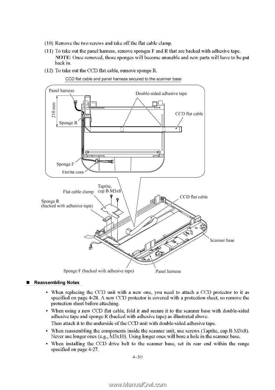
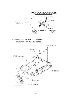
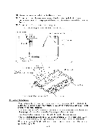
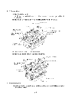
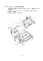
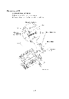
(10) Remove the two screws and take off the flat cable clamp. (11) To take out the panel harness, remove sponges F and R that are backed with adhesive tape. NOTE: Once removed, those sponges will become unusable and new parts will have to be put back in. (12) To take out the CCD flat cable, remove sponge R. CCD flat cable and panel harness secured to the scanner base Panel harness Double-sided adhesive tape Sponge R CCD flat cable 11 Sponge F Ferrite core Taptite, Flat cable clamp cup B M3x8 Sponge R (backed with adhesive tape) I ? CCD flat cable Scanner base Sponge F (backed with adhesive tape) Panel harness • Reassembling Notes • When replacing the CCD unit with a new one, you need to attach a CCD protector to it as specified on page 4-28. A new CCD protector is covered with a protection sheet, so remove the protection sheet before attaching. • When using a new CCD flat cable, fold it and secure it to the scanner base with double-sided adhesive tape and sponge R (backed with adhesive tape) as illustrated above. Then attach it to the underside of the CCD unit with double-sided adhesive tape. • When reassembling the components inside the scanner unit, use screws (Taptite, cup B M3x8). Never use longer ones (e.g., M3x10). Using longer ones will bore a hole in the scanner base. • When installing the CCD drive belt to the scanner base, set its rear end within the range specified on page 4-27. 4-30
-
 1
1 -
2
-
3
-
4
-
5
-
6
-
7
-
8
-
9
-
10
-
11
-
12
-
13
-
14
-
15
-
16
-
17
-
18
-
19
-
20
-
21
-
22
-
23
-
24
-
25
-
26
-
27
-
28
-
29
-
30
-
31
-
32
-
33
-
34
-
35
-
36
-
37
-
38
-
39
-
40
-
41
-
42
-
43
-
44
-
45
-
46
-
47
-
48
-
49
-
50
-
51
-
52
-
 53
53 -
 54
54 -
 55
55 -
 56
56 -
 57
57 -
 58
58 -
 59
59 -
 60
60 -
 61
61 -
 62
62 -
 63
63 -
64
-
65
-
66
-
67
-
68
-
69
-
70
-
71
-
72
-
73
-
74
-
75
-
76
-
77
-
78
-
79
-
80
-
81
-
82
-
83
-
84
-
85
-
86
-
87
-
88
-
89
-
90
-
91
-
92
-
93
-
94
-
95
-
96
-
97
-
98
-
99
-
100
-
101
-
102
-
103
-
104
-
105
-
106
-
107
-
108
-
109
-
110
-
111
-
112
-
113
-
114
-
115
-
116
-
117
-
118
-
119
-
120
-
121
-
122
-
123
-
124
-
125
-
126
-
127
-
128
-
129
-
130
-
131
-
132
-
133
-
134
-
135
-
136
-
137
-
138
-
139
-
140
-
141
-
142
-
143
-
144
-
145
-
146
-
147
-
148
-
149
-
150
-
151
-
152
-
153
-
154
-
155
-
156
-
157
-
158
-
159
-
160
-
161
-
162
-
163
-
164
-
165
-
166
-
167
-
168
-
169
-
170
-
171
-
172
-
173
-
174
-
175
-
176
-
177
-
178
-
179
-
180
-
181
-
182
-
183
-
184
-
185
-
186
-
187
-
188
-
189
-
190
-
191
-
192
-
193
-
194
-
195
-
196
-
197
-
198
-
199
-
200
-
201
-
202
-
203
-
204
 |
 |