Brother International DCP1000 Service Manual - Page 80
fixing, removed., heater, harness, cable, guides, provided, drive, unit., Remove, screws, motor.
 |
UPC - 012502565796
View all Brother International DCP1000 manuals
Add to My Manuals
Save this manual to your list of manuals |
Page 80 highlights
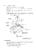
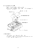
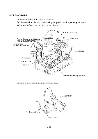
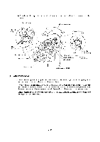
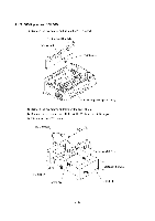
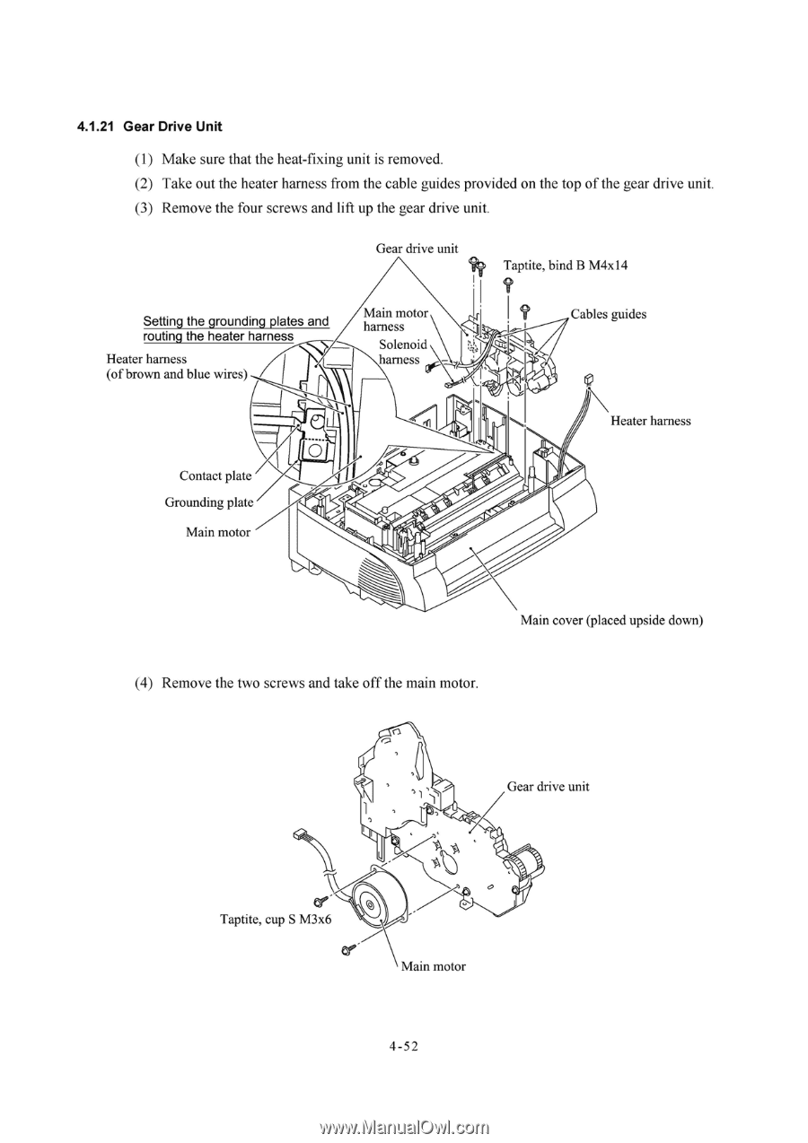
4.1.21 Gear Drive Unit (1) Make sure that the heat-fixing unit is removed. (2) Take out the heater harness from the cable guides provided on the top of the gear drive unit. (3) Remove the four screws and lift up the gear drive unit. Gear drive unit Setting the grounding plates and routing the heater harness Heater harness (of brown and blue wires) Main motor harness Solenoid harness Taptite, bind B M4x14 I Cables guides Heater harness Contact plate Grounding plate Main motor Main cover (placed upside down) (4) Remove the two screws and take off the main motor. Gear drive unit Taptite, cup S M3x6 Main motor 4-52
-
 1
1 -
2
-
3
-
4
-
5
-
6
-
7
-
8
-
9
-
10
-
11
-
12
-
13
-
14
-
15
-
16
-
17
-
18
-
19
-
20
-
21
-
22
-
23
-
24
-
25
-
26
-
27
-
28
-
29
-
30
-
31
-
32
-
33
-
34
-
35
-
36
-
37
-
38
-
39
-
40
-
41
-
42
-
43
-
44
-
45
-
46
-
47
-
48
-
49
-
50
-
51
-
52
-
53
-
54
-
55
-
56
-
57
-
58
-
59
-
60
-
61
-
62
-
63
-
64
-
65
-
66
-
67
-
68
-
69
-
70
-
71
-
72
-
73
-
74
-
 75
75 -
 76
76 -
 77
77 -
 78
78 -
 79
79 -
 80
80 -
 81
81 -
 82
82 -
 83
83 -
 84
84 -
 85
85 -
86
-
87
-
88
-
89
-
90
-
91
-
92
-
93
-
94
-
95
-
96
-
97
-
98
-
99
-
100
-
101
-
102
-
103
-
104
-
105
-
106
-
107
-
108
-
109
-
110
-
111
-
112
-
113
-
114
-
115
-
116
-
117
-
118
-
119
-
120
-
121
-
122
-
123
-
124
-
125
-
126
-
127
-
128
-
129
-
130
-
131
-
132
-
133
-
134
-
135
-
136
-
137
-
138
-
139
-
140
-
141
-
142
-
143
-
144
-
145
-
146
-
147
-
148
-
149
-
150
-
151
-
152
-
153
-
154
-
155
-
156
-
157
-
158
-
159
-
160
-
161
-
162
-
163
-
164
-
165
-
166
-
167
-
168
-
169
-
170
-
171
-
172
-
173
-
174
-
175
-
176
-
177
-
178
-
179
-
180
-
181
-
182
-
183
-
184
-
185
-
186
-
187
-
188
-
189
-
190
-
191
-
192
-
193
-
194
-
195
-
196
-
197
-
198
-
199
-
200
-
201
-
202
-
203
-
204
 |
 |
4.1.21
Gear
Drive
Unit
(1)
Make
sure
that
the
heat
-fixing
unit
is
removed.
(2)
Take
out
the
heater
harness
from
the
cable
guides
provided
on
the
top
of
the
gear
drive
unit.
(3)
Remove
the
four
screws
and
lift
up
the
gear
drive
unit.
Gear
drive
unit
Taptite,
bind
B
M4x14
I
Setting
the
grounding
plates
and
routing
the
heater
harness
Heater
harness
(of
brown
and
blue
wires)
Contact
plate
Grounding
plate
Main
motor
Main
motor
harness
Solenoid
harness
(4)
Remove
the
two
screws
and
take
off
the
main
motor.
Taptite,
cup
S
M3x6
Main
motor
4-52
Cables
guides
Heater
harness
Main
cover
(placed
upside
down)
Gear
drive
unit