Brother International DCP1000 Service Manual - Page 73
Setting, after, replacement
 |
UPC - 012502565796
View all Brother International DCP1000 manuals
Add to My Manuals
Save this manual to your list of manuals |
Page 73 highlights
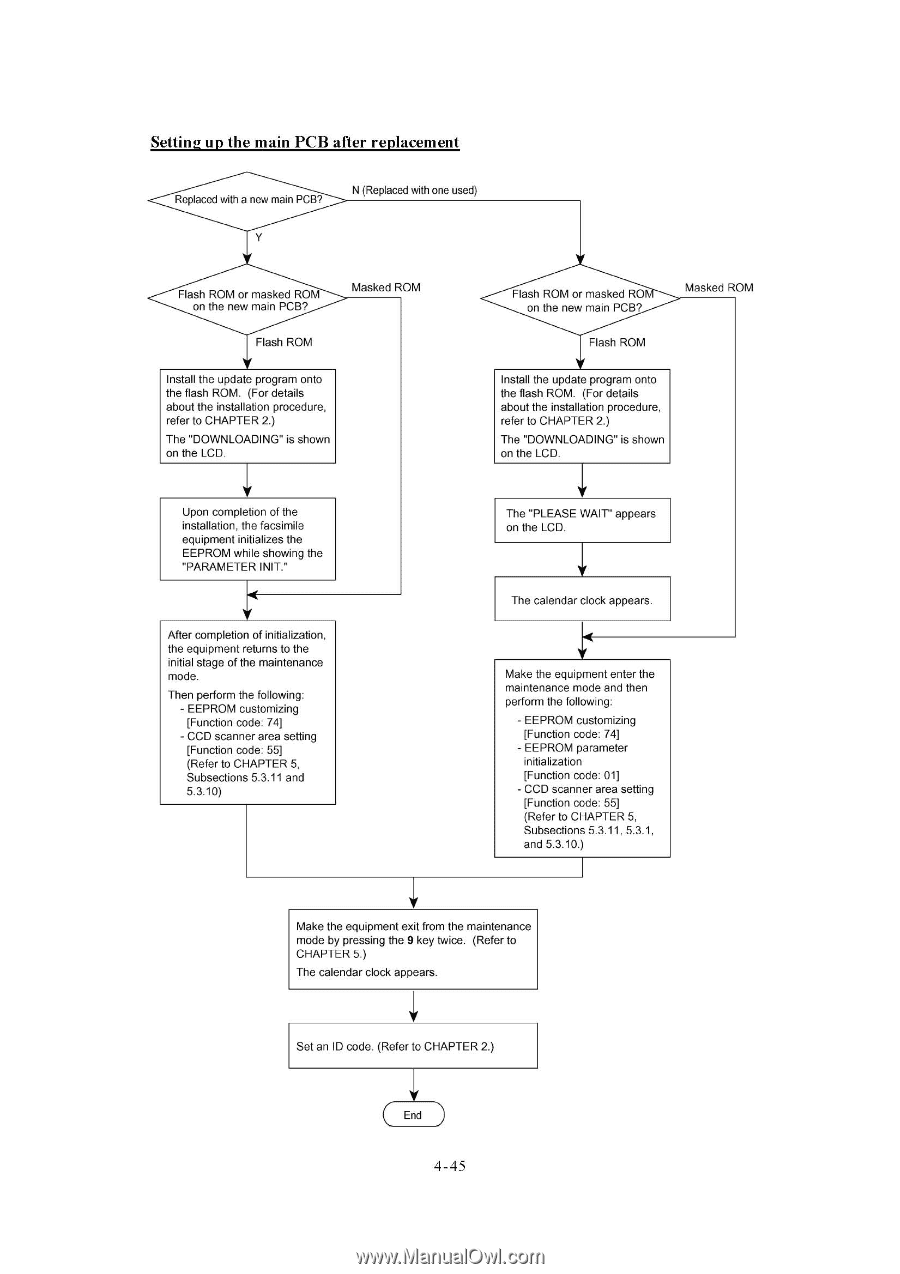
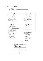
Setting up the main PCB after replacement Replaced with a new main PCB? N (Replaced with one used) Flash ROM or masked ROM on the new main PCB? Masked ROM Flash ROM Install the update program onto the flash ROM. (For details about the installation procedure, refer to CHAPTER 2.) The "DOWNLOADING" is shown on the LCD. Upon completion of the installation, the facsimile equipment initializes the EEPROM while showing the "PARAMETER INIT." After completion of initialization, the equipment returns to the initial stage of the maintenance mode. Then perform the following: - EEPROM customizing [Function code: 74] - CCD scanner area setting [Function code: 55] (Refer to CHAPTER 5, Subsections 5.3.11 and 5.3.10) Flash ROM or masked RO on the new main PCB? Flash ROM Masked ROM Install the update program onto the flash ROM. (For details about the installation procedure, refer to CHAPTER 2.) The "DOWNLOADING" is shown on the LCD. The "PLEASE WAIT" appears on the LCD. The calendar clock appears. `4 Make the equipment enter the maintenance mode and then perform the following: - EEPROM customizing [Function code: 74] - EEPROM parameter initialization [Function code: 01] CCD scanner area setting [Function code: 55] (Refer to CHAPTER 5, Subsections 5.3.11, 5.3.1, and 5.3.10.) Make the equipment exit from the maintenance mode by pressing the 9 key twice. (Refer to CHAPTER 5.) The calendar clock appears. Set an ID code. (Refer to CHAPTER 2.) End 4-45
-
 1
1 -
2
-
3
-
4
-
5
-
6
-
7
-
8
-
9
-
10
-
11
-
12
-
13
-
14
-
15
-
16
-
17
-
18
-
19
-
20
-
21
-
22
-
23
-
24
-
25
-
26
-
27
-
28
-
29
-
30
-
31
-
32
-
33
-
34
-
35
-
36
-
37
-
38
-
39
-
40
-
41
-
42
-
43
-
44
-
45
-
46
-
47
-
48
-
49
-
50
-
51
-
52
-
53
-
54
-
55
-
56
-
57
-
58
-
59
-
60
-
61
-
62
-
63
-
64
-
65
-
66
-
67
-
 68
68 -
 69
69 -
 70
70 -
 71
71 -
 72
72 -
 73
73 -
 74
74 -
 75
75 -
 76
76 -
 77
77 -
 78
78 -
79
-
80
-
81
-
82
-
83
-
84
-
85
-
86
-
87
-
88
-
89
-
90
-
91
-
92
-
93
-
94
-
95
-
96
-
97
-
98
-
99
-
100
-
101
-
102
-
103
-
104
-
105
-
106
-
107
-
108
-
109
-
110
-
111
-
112
-
113
-
114
-
115
-
116
-
117
-
118
-
119
-
120
-
121
-
122
-
123
-
124
-
125
-
126
-
127
-
128
-
129
-
130
-
131
-
132
-
133
-
134
-
135
-
136
-
137
-
138
-
139
-
140
-
141
-
142
-
143
-
144
-
145
-
146
-
147
-
148
-
149
-
150
-
151
-
152
-
153
-
154
-
155
-
156
-
157
-
158
-
159
-
160
-
161
-
162
-
163
-
164
-
165
-
166
-
167
-
168
-
169
-
170
-
171
-
172
-
173
-
174
-
175
-
176
-
177
-
178
-
179
-
180
-
181
-
182
-
183
-
184
-
185
-
186
-
187
-
188
-
189
-
190
-
191
-
192
-
193
-
194
-
195
-
196
-
197
-
198
-
199
-
200
-
201
-
202
-
203
-
204
 |
 |