Brother International DCP1000 Service Manual - Page 77
Brother International DCP1000 - DCP 1000 B/W Laser Manual
 |
UPC - 012502565796
View all Brother International DCP1000 manuals
Add to My Manuals
Save this manual to your list of manuals |
Page 77 highlights
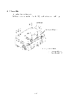
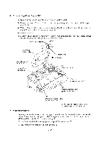
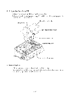
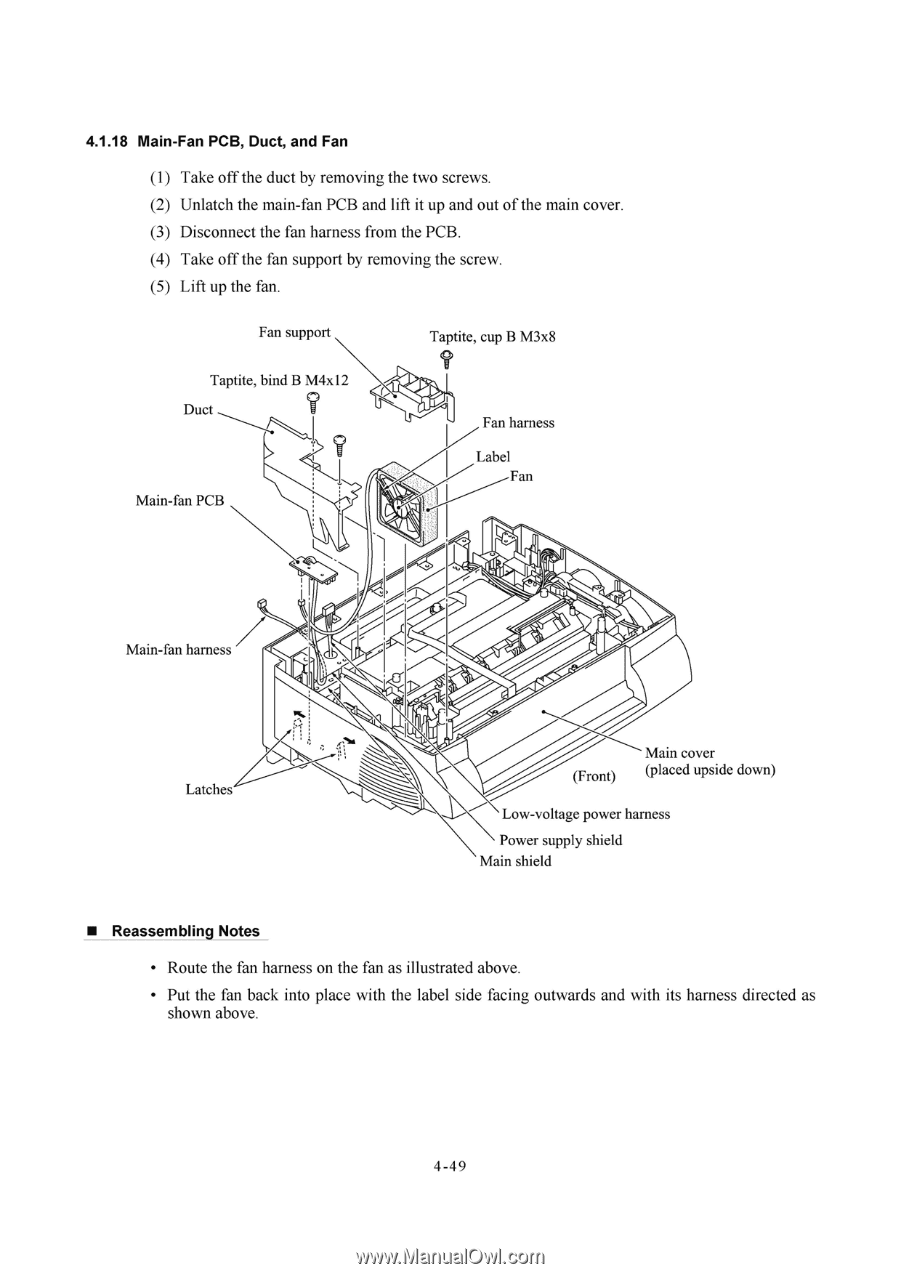
4.1.18 Main-Fan PCB, Duct, and Fan (1) Take off the duct by removing the two screws. (2) Unlatch the main-fan PCB and lift it up and out of the main cover. (3) Disconnect the fan harness from the PCB. (4) Take off the fan support by removing the screw. (5) Lift up the fan. Fan support Taptite, cup B M3x8 Taptite, bind B M4x12 Duct Main-fan PCB Fan harness Label Fan Main-fan harness I Latches Main cover (Front) (placed upside down) Low-voltage power harness Power supply shield Main shield • Reassembling Notes • Route the fan harness on the fan as illustrated above. • Put the fan back into place with the label side facing outwards and with its harness directed as shown above. 4 -4 9
-
 1
1 -
2
-
3
-
4
-
5
-
6
-
7
-
8
-
9
-
10
-
11
-
12
-
13
-
14
-
15
-
16
-
17
-
18
-
19
-
20
-
21
-
22
-
23
-
24
-
25
-
26
-
27
-
28
-
29
-
30
-
31
-
32
-
33
-
34
-
35
-
36
-
37
-
38
-
39
-
40
-
41
-
42
-
43
-
44
-
45
-
46
-
47
-
48
-
49
-
50
-
51
-
52
-
53
-
54
-
55
-
56
-
57
-
58
-
59
-
60
-
61
-
62
-
63
-
64
-
65
-
66
-
67
-
68
-
69
-
70
-
71
-
 72
72 -
 73
73 -
 74
74 -
 75
75 -
 76
76 -
 77
77 -
 78
78 -
 79
79 -
 80
80 -
 81
81 -
 82
82 -
83
-
84
-
85
-
86
-
87
-
88
-
89
-
90
-
91
-
92
-
93
-
94
-
95
-
96
-
97
-
98
-
99
-
100
-
101
-
102
-
103
-
104
-
105
-
106
-
107
-
108
-
109
-
110
-
111
-
112
-
113
-
114
-
115
-
116
-
117
-
118
-
119
-
120
-
121
-
122
-
123
-
124
-
125
-
126
-
127
-
128
-
129
-
130
-
131
-
132
-
133
-
134
-
135
-
136
-
137
-
138
-
139
-
140
-
141
-
142
-
143
-
144
-
145
-
146
-
147
-
148
-
149
-
150
-
151
-
152
-
153
-
154
-
155
-
156
-
157
-
158
-
159
-
160
-
161
-
162
-
163
-
164
-
165
-
166
-
167
-
168
-
169
-
170
-
171
-
172
-
173
-
174
-
175
-
176
-
177
-
178
-
179
-
180
-
181
-
182
-
183
-
184
-
185
-
186
-
187
-
188
-
189
-
190
-
191
-
192
-
193
-
194
-
195
-
196
-
197
-
198
-
199
-
200
-
201
-
202
-
203
-
204
 |
 |
4.1.18
Main
-Fan
PCB,
Duct,
and
Fan
(1)
Take
off
the
duct
by
removing
the
two
screws.
(2)
Unlatch
the
main
-fan
PCB
and
lift
it
up
and
out
of
the
main
cover.
(3)
Disconnect
the
fan
harness
from
the
PCB.
(4)
Take
off
the
fan
support
by
removing
the
screw.
(5)
Lift
up
the
fan.
Fan
support
Taptite,
bind
B
M4x12
Duct
Main
-fan
PCB
Main
-fan
harness
Latches
•
Reassembling
Notes
I
Taptite,
cup
B
M3x8
Fan
harness
Label
Fan
Main
cover
(Front)
(placed
upside
down)
Low
-voltage
power
harness
Power
supply
shield
Main
shield
•
Route
the
fan
harness
on
the
fan
as
illustrated
above.
•
Put
the
fan
back
into
place
with
the
label
side
facing
outwards
and
with
its
harness
directed
as
shown
above.
4
-4
9