Brother International DCP1000 Service Manual - Page 75
supply PCB
 |
UPC - 012502565796
View all Brother International DCP1000 manuals
Add to My Manuals
Save this manual to your list of manuals |
Page 75 highlights
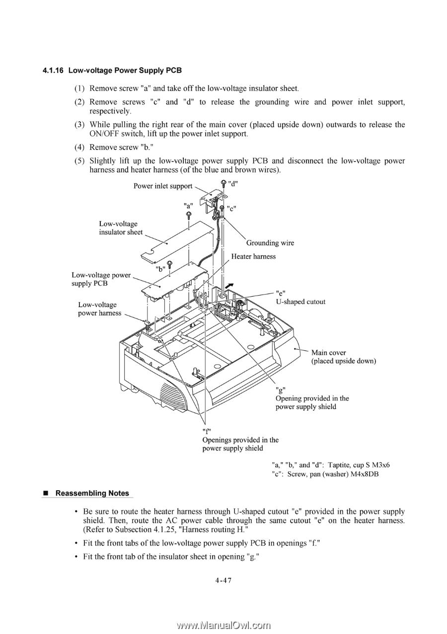
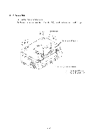
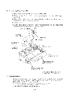
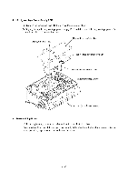
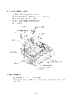
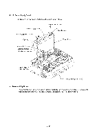
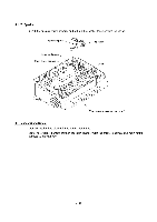
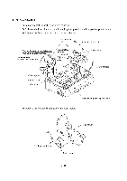
4.1.16 Low-voltage Power Supply PCB (1) Remove screw "a" and take off the low-voltage insulator sheet. (2) Remove screws "c" and "d" to release the grounding wire and power inlet support, respectively. (3) While pulling the right rear of the main cover (placed upside down) outwards to release the ON/OFF switch, lift up the power inlet support. (4) Remove screw "b." (5) Slightly lift up the low-voltage power supply PCB and disconnect the low-voltage power harness and heater harness (of the blue and brown wires). Power inlet support ? u Low-voltage insulator sheet Low-voltage power supply PCB Low-voltage power harness 1 Grounding wire Heater harness !l e t/ U-shaped cutout Main cover (placed upside down) lI g ll Opening provided in the power supply shield Openings provided in the power supply shield "a," "b," and "d": Taptite, cup S M3x6 "c": Screw, pan (washer) M4x8DB ■ Reassembling Notes • Be sure to route the heater harness through U-shaped cutout "e" provided in the power supply shield. Then, route the AC power cable through the same cutout "e" on the heater harness. (Refer to Subsection 4.1.25, "Harness routing H." • Fit the front tabs of the low-voltage power supply PCB in openings "f." • Fit the front tab of the insulator sheet in opening "g." 4 -4 7
-
 1
1 -
2
-
3
-
4
-
5
-
6
-
7
-
8
-
9
-
10
-
11
-
12
-
13
-
14
-
15
-
16
-
17
-
18
-
19
-
20
-
21
-
22
-
23
-
24
-
25
-
26
-
27
-
28
-
29
-
30
-
31
-
32
-
33
-
34
-
35
-
36
-
37
-
38
-
39
-
40
-
41
-
42
-
43
-
44
-
45
-
46
-
47
-
48
-
49
-
50
-
51
-
52
-
53
-
54
-
55
-
56
-
57
-
58
-
59
-
60
-
61
-
62
-
63
-
64
-
65
-
66
-
67
-
68
-
69
-
 70
70 -
 71
71 -
 72
72 -
 73
73 -
 74
74 -
 75
75 -
 76
76 -
 77
77 -
 78
78 -
 79
79 -
 80
80 -
81
-
82
-
83
-
84
-
85
-
86
-
87
-
88
-
89
-
90
-
91
-
92
-
93
-
94
-
95
-
96
-
97
-
98
-
99
-
100
-
101
-
102
-
103
-
104
-
105
-
106
-
107
-
108
-
109
-
110
-
111
-
112
-
113
-
114
-
115
-
116
-
117
-
118
-
119
-
120
-
121
-
122
-
123
-
124
-
125
-
126
-
127
-
128
-
129
-
130
-
131
-
132
-
133
-
134
-
135
-
136
-
137
-
138
-
139
-
140
-
141
-
142
-
143
-
144
-
145
-
146
-
147
-
148
-
149
-
150
-
151
-
152
-
153
-
154
-
155
-
156
-
157
-
158
-
159
-
160
-
161
-
162
-
163
-
164
-
165
-
166
-
167
-
168
-
169
-
170
-
171
-
172
-
173
-
174
-
175
-
176
-
177
-
178
-
179
-
180
-
181
-
182
-
183
-
184
-
185
-
186
-
187
-
188
-
189
-
190
-
191
-
192
-
193
-
194
-
195
-
196
-
197
-
198
-
199
-
200
-
201
-
202
-
203
-
204
 |
 |