Brother International DCP1000 Service Manual - Page 94
Maintenance, Contents
 |
UPC - 012502565796
View all Brother International DCP1000 manuals
Add to My Manuals
Save this manual to your list of manuals |
Page 94 highlights
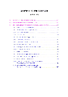
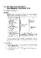
CHAPTER 5 MAINTENANCE MODE CONTENTS 5.1 ENTRY INTO THE MAINTENANCE MODE 5.2 LIST OF MAINTENANCE-MODE FUNCTIONS 5.3 DETAILED DESCRIPTION OF MAINTENANCE-MODE FUNCTIONS 5.3.1 EEPROM Parameter Initialization 5.3.2 Printout of Scanning Compensation Data 5.3.3 ADF Performance Test 5.3.4 Test Pattern 1 5.3.5 Firmware Switch Setting and Printout 5.3.6 Operational Check of LCD 5.3.7 Operational Check of Control Panel PCB 5.3.8 Sensor Operational Check 5.3.9 Fine Adjustment of Scanning Start/End Position 5.3.10 CCD Scanner Area Setting 5.3.11 EEPROM Customizing 5.3.12 Printout of the Equipment's Log Information 5.3.13 Display of the Equipment's Log Information 5.3.14 Equipment Error Code Indication 5.3.15 Output of Transmission Log to the Telephone Line (Not applicable to machines w/o fax) 5.3.16 Cancellation of the Memory Security Mode (Applicable to the European version w/ fax only) 5-1 5-2 5-4 5-4 5-5 5-7 5-8 5-9 5-12 5-12 5-14 5-15 5-16 5-16 5-17 5-17 5-18 5-18 5-19
-
 1
1 -
2
-
3
-
4
-
5
-
6
-
7
-
8
-
9
-
10
-
11
-
12
-
13
-
14
-
15
-
16
-
17
-
18
-
19
-
20
-
21
-
22
-
23
-
24
-
25
-
26
-
27
-
28
-
29
-
30
-
31
-
32
-
33
-
34
-
35
-
36
-
37
-
38
-
39
-
40
-
41
-
42
-
43
-
44
-
45
-
46
-
47
-
48
-
49
-
50
-
51
-
52
-
53
-
54
-
55
-
56
-
57
-
58
-
59
-
60
-
61
-
62
-
63
-
64
-
65
-
66
-
67
-
68
-
69
-
70
-
71
-
72
-
73
-
74
-
75
-
76
-
77
-
78
-
79
-
80
-
81
-
82
-
83
-
84
-
85
-
86
-
87
-
88
-
 89
89 -
 90
90 -
 91
91 -
 92
92 -
 93
93 -
 94
94 -
 95
95 -
 96
96 -
 97
97 -
 98
98 -
 99
99 -
100
-
101
-
102
-
103
-
104
-
105
-
106
-
107
-
108
-
109
-
110
-
111
-
112
-
113
-
114
-
115
-
116
-
117
-
118
-
119
-
120
-
121
-
122
-
123
-
124
-
125
-
126
-
127
-
128
-
129
-
130
-
131
-
132
-
133
-
134
-
135
-
136
-
137
-
138
-
139
-
140
-
141
-
142
-
143
-
144
-
145
-
146
-
147
-
148
-
149
-
150
-
151
-
152
-
153
-
154
-
155
-
156
-
157
-
158
-
159
-
160
-
161
-
162
-
163
-
164
-
165
-
166
-
167
-
168
-
169
-
170
-
171
-
172
-
173
-
174
-
175
-
176
-
177
-
178
-
179
-
180
-
181
-
182
-
183
-
184
-
185
-
186
-
187
-
188
-
189
-
190
-
191
-
192
-
193
-
194
-
195
-
196
-
197
-
198
-
199
-
200
-
201
-
202
-
203
-
204
 |
 |