Brother International DCP1000 Service Manual - Page 33
Aiquiessesm
 |
UPC - 012502565796
View all Brother International DCP1000 manuals
Add to My Manuals
Save this manual to your list of manuals |
Page 33 highlights
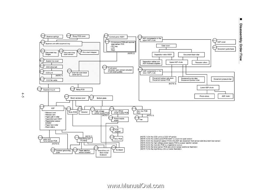
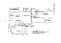
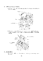
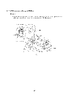
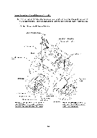
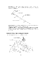
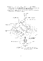
■ mold Jam) Aiquiessesm () Scanner springs C) Scanner unit with document tray 9Document tray Hinges c)Document tray open sensor C) Document stopper (1) Scaner top cover CCD drive belt I CCD unit (NOTE 1 .1.7 CCD flat cable c) Scanner open lever Lever spring Scanner mount .1 9 Relay PCB C) Control panel ASSY 0 - Control panel PCB with scanner open sensor PCB - FPC key -LCD - Keys (NOTE 2) 4.1. ADF components on the upper ADF chute Gear cover Separation roller ASSY Document feed roller (7)ADF cover • Document guide base y Front cover (Scanner open sensor actuator) Front cover guides Separation rubber unit ADF thickness adjuster Upper ADF chute Pressure rollers y ADF components on the lower ADF chute Document sensor actuators Document sensor PCB (NOTE 3) Document guide clips Document ejection roller Document pressure bar Lower ADF chute Board access cover Bottom plate Pinch rollers ADF motor ASF - Release lever - Release cam - Paper pull-in roller - Separation pad ASSY - Registration sensor actuator - Paper feed roller - Pinch rollers Main PCB Speaker • High-vol age power supply PCB (NOTE 4) Low-voltage power supply PCB * (:;) PCB support y laser unit Toner sensor PCB (NOTE 6) CI) (NOTE 7) Heat fixing unit -FU lamp NCU PCB i) Cr Scanner grounding ) Paper ejection plate sensor actuator 2 Gear drive unit - Main motor - Solenoid 1.2 EL board 9Main-fan PCB Duct (NOTE 5) ( Sr- i ) Fan (NOTE 1) On the CCD unit is a CCD HP sensor. (NOTE 2) On the control panel PCB ASSY is a scanner open sensor. (NOTE 3) On the document sensor PCB in the ADF are document front sensor and document rear sensor. (NOTE 4) On the high-voltage power supply PCB iS e paper ejection Seiner. (NOTE 5) On the main-fan PCB is a registration sensor. (NOTE 6) On the toner sensor PCB are a toner sensor and toner therrnistor. (NOTE 7) On the heat-fixing unit is a heater thermistor.
-
 1
1 -
2
-
3
-
4
-
5
-
6
-
7
-
8
-
9
-
10
-
11
-
12
-
13
-
14
-
15
-
16
-
17
-
18
-
19
-
20
-
21
-
22
-
23
-
24
-
25
-
26
-
27
-
 28
28 -
 29
29 -
 30
30 -
 31
31 -
 32
32 -
 33
33 -
 34
34 -
 35
35 -
 36
36 -
 37
37 -
 38
38 -
39
-
40
-
41
-
42
-
43
-
44
-
45
-
46
-
47
-
48
-
49
-
50
-
51
-
52
-
53
-
54
-
55
-
56
-
57
-
58
-
59
-
60
-
61
-
62
-
63
-
64
-
65
-
66
-
67
-
68
-
69
-
70
-
71
-
72
-
73
-
74
-
75
-
76
-
77
-
78
-
79
-
80
-
81
-
82
-
83
-
84
-
85
-
86
-
87
-
88
-
89
-
90
-
91
-
92
-
93
-
94
-
95
-
96
-
97
-
98
-
99
-
100
-
101
-
102
-
103
-
104
-
105
-
106
-
107
-
108
-
109
-
110
-
111
-
112
-
113
-
114
-
115
-
116
-
117
-
118
-
119
-
120
-
121
-
122
-
123
-
124
-
125
-
126
-
127
-
128
-
129
-
130
-
131
-
132
-
133
-
134
-
135
-
136
-
137
-
138
-
139
-
140
-
141
-
142
-
143
-
144
-
145
-
146
-
147
-
148
-
149
-
150
-
151
-
152
-
153
-
154
-
155
-
156
-
157
-
158
-
159
-
160
-
161
-
162
-
163
-
164
-
165
-
166
-
167
-
168
-
169
-
170
-
171
-
172
-
173
-
174
-
175
-
176
-
177
-
178
-
179
-
180
-
181
-
182
-
183
-
184
-
185
-
186
-
187
-
188
-
189
-
190
-
191
-
192
-
193
-
194
-
195
-
196
-
197
-
198
-
199
-
200
-
201
-
202
-
203
-
204
 |
 |