Brother International DCP1000 Service Manual - Page 134
received, image, problem, first, facsimile, equipment., copied, normal, problem, remote, terminal,
 |
UPC - 012502565796
View all Brother International DCP1000 manuals
Add to My Manuals
Save this manual to your list of manuals |
Page 134 highlights
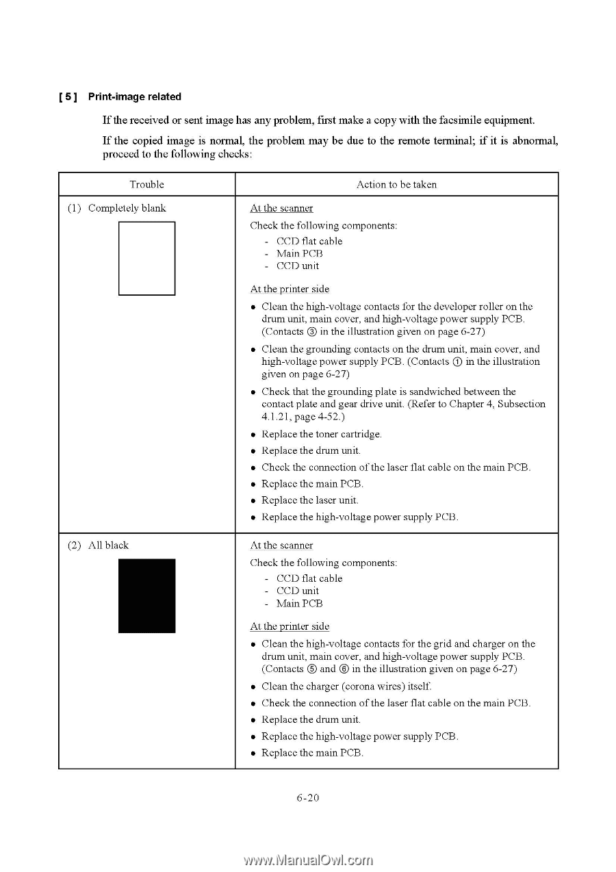
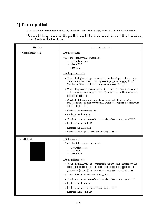
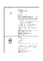
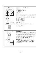
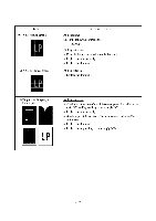
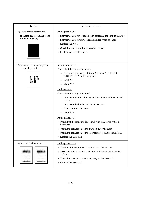
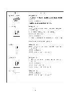
[ 5 ] Print-image related If the received or sent image has any problem, first make a copy with the facsimile equipment. If the copied image is normal, the problem may be due to the remote terminal; if it is abnormal, proceed to the following checks: Trouble (1) Completely blank (2) All black Action to be taken At the scanner Check the following components: - CCD flat cable - Main PCB - CCD unit At the printer side • Clean the high-voltage contacts for the developer roller on the drum unit, main cover, and high-voltage power supply PCB. (Contacts ® in the illustration given on page 6-27) • Clean the grounding contacts on the drum unit, main cover, and high-voltage power supply PCB. (Contacts C) in the illustration given on page 6-27) • Check that the grounding plate is sandwiched between the contact plate and gear drive unit. (Refer to Chapter 4, Subsection 4.1.21, page 4-52.) • Replace the toner cartridge. • Replace the drum unit. • Check the connection of the laser flat cable on the main PCB. • Replace the main PCB. • Replace the laser unit. • Replace the high-voltage power supply PCB. , At the scanner Check the following components: - CCD flat cable - CCD unit - Main PCB At the printer side • Clean the high-voltage contacts for the grid and charger on the drum unit, main cover, and high-voltage power supply PCB. (Contacts ® and © in the illustration given on page 6-27) • Clean the charger (corona wires) itself • Check the connection of the laser flat cable on the main PCB. • Replace the drum unit. • Replace the high-voltage power supply PCB. • Replace the main PCB. 6-20
-
 1
1 -
2
-
3
-
4
-
5
-
6
-
7
-
8
-
9
-
10
-
11
-
12
-
13
-
14
-
15
-
16
-
17
-
18
-
19
-
20
-
21
-
22
-
23
-
24
-
25
-
26
-
27
-
28
-
29
-
30
-
31
-
32
-
33
-
34
-
35
-
36
-
37
-
38
-
39
-
40
-
41
-
42
-
43
-
44
-
45
-
46
-
47
-
48
-
49
-
50
-
51
-
52
-
53
-
54
-
55
-
56
-
57
-
58
-
59
-
60
-
61
-
62
-
63
-
64
-
65
-
66
-
67
-
68
-
69
-
70
-
71
-
72
-
73
-
74
-
75
-
76
-
77
-
78
-
79
-
80
-
81
-
82
-
83
-
84
-
85
-
86
-
87
-
88
-
89
-
90
-
91
-
92
-
93
-
94
-
95
-
96
-
97
-
98
-
99
-
100
-
101
-
102
-
103
-
104
-
105
-
106
-
107
-
108
-
109
-
110
-
111
-
112
-
113
-
114
-
115
-
116
-
117
-
118
-
119
-
120
-
121
-
122
-
123
-
124
-
125
-
126
-
127
-
128
-
 129
129 -
 130
130 -
 131
131 -
 132
132 -
 133
133 -
 134
134 -
 135
135 -
 136
136 -
 137
137 -
 138
138 -
 139
139 -
140
-
141
-
142
-
143
-
144
-
145
-
146
-
147
-
148
-
149
-
150
-
151
-
152
-
153
-
154
-
155
-
156
-
157
-
158
-
159
-
160
-
161
-
162
-
163
-
164
-
165
-
166
-
167
-
168
-
169
-
170
-
171
-
172
-
173
-
174
-
175
-
176
-
177
-
178
-
179
-
180
-
181
-
182
-
183
-
184
-
185
-
186
-
187
-
188
-
189
-
190
-
191
-
192
-
193
-
194
-
195
-
196
-
197
-
198
-
199
-
200
-
201
-
202
-
203
-
204
 |
 |