Brother International DCP1000 Service Manual - Page 61
°<
 |
UPC - 012502565796
View all Brother International DCP1000 manuals
Add to My Manuals
Save this manual to your list of manuals |
Page 61 highlights
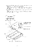
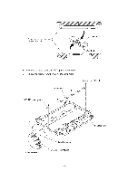
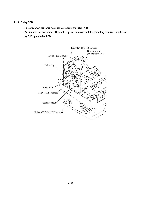
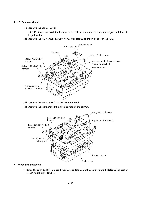
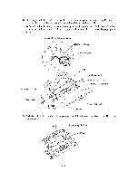
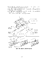
4.1.10 Scanner Mount (1) Remove the harness cover. NOTE: Once removed, the harness cover will become unusable and a new part will have to be put back in. (2) Remove the relay (ADF) harness from seven latches and then bring it to the right. Harness cover Adhesive tape Relay (CCD/SEN) harness Relay (CCD/PANEL) harness 7 latches Relay (ADF) harness Area where the harness cover should be attached Scanner mount Grouding wire (To the main PCB) 00 O (3) Remove the two screws from the scanner mount (4) Remove the scanner mount in the direction of the arrows. Relay (ADF) harness °
-
 1
1 -
2
-
3
-
4
-
5
-
6
-
7
-
8
-
9
-
10
-
11
-
12
-
13
-
14
-
15
-
16
-
17
-
18
-
19
-
20
-
21
-
22
-
23
-
24
-
25
-
26
-
27
-
28
-
29
-
30
-
31
-
32
-
33
-
34
-
35
-
36
-
37
-
38
-
39
-
40
-
41
-
42
-
43
-
44
-
45
-
46
-
47
-
48
-
49
-
50
-
51
-
52
-
53
-
54
-
55
-
 56
56 -
 57
57 -
 58
58 -
 59
59 -
 60
60 -
 61
61 -
 62
62 -
 63
63 -
 64
64 -
 65
65 -
 66
66 -
67
-
68
-
69
-
70
-
71
-
72
-
73
-
74
-
75
-
76
-
77
-
78
-
79
-
80
-
81
-
82
-
83
-
84
-
85
-
86
-
87
-
88
-
89
-
90
-
91
-
92
-
93
-
94
-
95
-
96
-
97
-
98
-
99
-
100
-
101
-
102
-
103
-
104
-
105
-
106
-
107
-
108
-
109
-
110
-
111
-
112
-
113
-
114
-
115
-
116
-
117
-
118
-
119
-
120
-
121
-
122
-
123
-
124
-
125
-
126
-
127
-
128
-
129
-
130
-
131
-
132
-
133
-
134
-
135
-
136
-
137
-
138
-
139
-
140
-
141
-
142
-
143
-
144
-
145
-
146
-
147
-
148
-
149
-
150
-
151
-
152
-
153
-
154
-
155
-
156
-
157
-
158
-
159
-
160
-
161
-
162
-
163
-
164
-
165
-
166
-
167
-
168
-
169
-
170
-
171
-
172
-
173
-
174
-
175
-
176
-
177
-
178
-
179
-
180
-
181
-
182
-
183
-
184
-
185
-
186
-
187
-
188
-
189
-
190
-
191
-
192
-
193
-
194
-
195
-
196
-
197
-
198
-
199
-
200
-
201
-
202
-
203
-
204
 |
 |
4.1.10
Scanner
Mount
(1)
Remove
the
harness
cover.
NOTE:
Once
removed,
the
harness
cover
will
become
unusable
and
a
new
part
will
have
to
be
put
back
in.
(2)
Remove
the
relay
(ADF)
harness
from
seven
latches
and
then
bring
it
to
the
right.
Harness
cover
Adhesive
tape
7
latches
Relay
(ADF)
harness
Relay
(CCD/SEN)
harness
Relay
(CCD/PANEL)
harness
O
Grouding
wire
(To
the
main
PCB)
00
(3)
Remove
the
two
screws
from
the
scanner
mount
(4)
Remove
the
scanner
mount
in
the
direction
of
the
arrows.
Relay
(CCD/SEN)
harness
Relay
(CCD/PANEL)
harness
Grounding
wire
Cable
guide
■
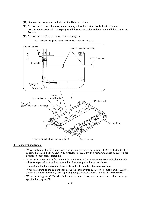
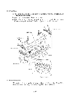
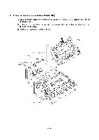
Reassembling
Notes
°<\
Area
where
the
harness
cover
should
be
attached
Scanner
mount
Relay
(ADF)
harness
Taptite,
bind
B
M4x12
Scanner
mount
Main
cover
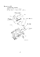
•
Route
the
relay
(ADF)
harness
through
seven
latches
on
the
scanner
mount.
Refer
to
Subsection
4.1.25,
"Harness
routing
C."
4-33