Canon FAXPHONE B540 User Guide - Page 17
Gonnecting the AG power cord
 |
View all Canon FAXPHONE B540 manuals
Add to My Manuals
Save this manual to your list of manuals |
Page 17 highlights
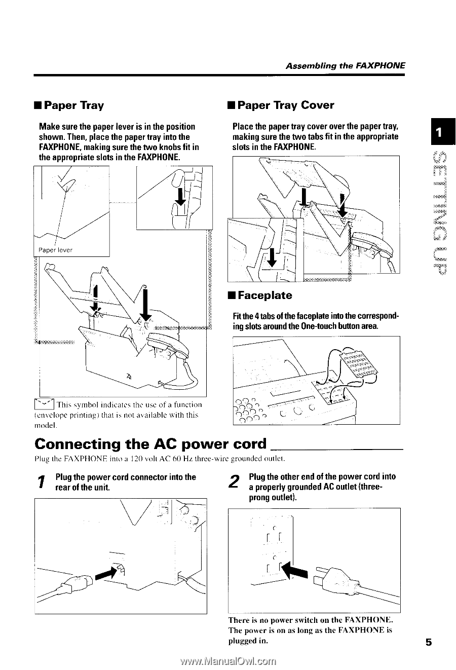
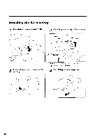
Assembling the FAXPHONE I Paper Tray Makesurethepapelreveris intheposition shownT. henp, lacethepapetrrayintothe FAXPH0NmEa, kingsurethetwoknohsfit in t h ea p p r o p r i ast el o t si n t h eF A X P H 0 N E . I Paper Tray Cover Placethepapetrlaycoverovelthepapertray, makingsurethetwotabsfit intheappropriate s l o t si n t h eF A X P H 0 N E . ! {;l3 iTT '*{ cxd; ffi frlr f.ftir, I Faceplate Fitttre4tabsofthefaceplateintothecorespondingslotsaroundtheOne-toucbhuttonarea. F 1 rnlr symbolindicatesthe useof a function ( e n v e l o pper i n t i n g )t h a ti s n o t a v a i l a b l ew i t h t h i s rnodel. Gonnecting the AG power cord PlugtheFAXPHONEintoa 120volt AC 60 Hz three-wiregroundedoullet 7 I Plugthepowercordconnectoinr tothe tearoftheunit. I t Plugtheotherendofthepowercordinto a properlgyroundeAdCoutle(tthree- prongoutlet). There is no power switch on the FAXPHONE. The power is on as long as the FAXPHONE is plugged in. 5
-
 1
1 -
2
-
3
-
4
-
5
-
6
-
7
-
8
-
9
-
10
-
11
-
 12
12 -
 13
13 -
 14
14 -
 15
15 -
 16
16 -
 17
17 -
 18
18 -
 19
19 -
 20
20 -
 21
21 -
 22
22 -
23
-
24
-
25
-
26
-
27
-
28
-
29
-
30
-
31
-
32
-
33
-
34
-
35
-
36
-
37
-
38
-
39
-
40
-
41
-
42
-
43
-
44
-
45
-
46
-
47
-
48
-
49
-
50
-
51
-
52
-
53
-
54
-
55
-
56
-
57
-
58
-
59
-
60
-
61
-
62
-
63
-
64
-
65
-
66
-
67
-
68
-
69
-
70
-
71
-
72
-
73
-
74
-
75
-
76
-
77
-
78
-
79
-
80
-
81
-
82
-
83
-
84
-
85
-
86
-
87
-
88
-
89
-
90
-
91
-
92
-
93
-
94
-
95
-
96
-
97
-
98
-
99
-
100
-
101
-
102
-
103
-
104
-
105
-
106
-
107
-
108
-
109
-
110
-
111
-
112
-
113
-
114
-
115
-
116
-
117
-
118
-
119
-
120
-
121
-
122
-
123
-
124
-
125
-
126
-
127
-
128
-
129
-
130
-
131
-
132
-
133
-
134
-
135
-
136
 |
 |