Dell PowerEdge C6300 Dell PowerEdge C6320 Owners Manual - Page 104
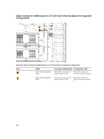
Cable routing for middle plane to direct hard-drive backplane, Related Information, Cable
 |
View all Dell PowerEdge C6300 manuals
Add to My Manuals
Save this manual to your list of manuals |
Page 104 highlights
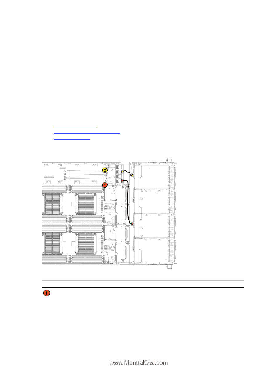
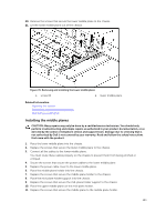
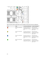
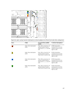
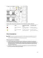
12. Connect all the cables to the upper middle plane. You must route these cables properly on the chassis to prevent them from being pinched or crimped. 13. Secure the screws that secure the power cables to the upper middle plane. 14. Replace the power cable cover to the upper lower middle plane. 15. Place the middle-wall bracket into the chassis. 16. Replace the screws that secure the middle-wall bracket to the chassis. 17. Replace the cooling-fan cage. Replace the cooling fans. 18. Replace the system-board assemblies. 19. Close the system. 20. Reconnect the system to its electrical outlet and turn on the system, including any attached peripherals. Related Information Installing a cooling fan Installing a system-board assembly Closing the system Cable routing for middle plane to direct hard-drive backplane Figure 77. Cable routing−top middle plane to direct backplane for 12 x3.5 inch hard-drive configuration Item Cable Hard-drive backplane cable From (top Middle Plane) To (direct backplane) mini-SAS connector for SATA2 hard drive system board 1 and 2 connectors 1, 2 and 3 104
-
 1
1 -
2
-
3
-
4
-
5
-
6
-
7
-
8
-
9
-
10
-
11
-
12
-
13
-
14
-
15
-
16
-
17
-
18
-
19
-
20
-
21
-
22
-
23
-
24
-
25
-
26
-
27
-
28
-
29
-
30
-
31
-
32
-
33
-
34
-
35
-
36
-
37
-
38
-
39
-
40
-
41
-
42
-
43
-
44
-
45
-
46
-
47
-
48
-
49
-
50
-
51
-
52
-
53
-
54
-
55
-
56
-
57
-
58
-
59
-
60
-
61
-
62
-
63
-
64
-
65
-
66
-
67
-
68
-
69
-
70
-
71
-
72
-
73
-
74
-
75
-
76
-
77
-
78
-
79
-
80
-
81
-
82
-
83
-
84
-
85
-
86
-
87
-
88
-
89
-
90
-
91
-
92
-
93
-
94
-
95
-
96
-
97
-
98
-
 99
99 -
 100
100 -
 101
101 -
 102
102 -
 103
103 -
 104
104 -
 105
105 -
 106
106 -
 107
107 -
 108
108 -
 109
109 -
110
-
111
-
112
-
113
-
114
-
115
-
116
-
117
-
118
-
119
-
120
-
121
-
122
-
123
-
124
-
125
-
126
-
127
-
128
-
129
-
130
-
131
-
132
-
133
-
134
-
135
-
136
-
137
-
138
-
139
-
140
-
141
-
142
-
143
-
144
-
145
-
146
-
147
-
148
 |
 |